| T O P I C R E V I E W |
| PiR |
Posted - 03/08/2022 : 08:47:22
Edit: the problem seemed to be an old defective (end of life) M4011 tube. All voltage measures I made are subject to caution.
The tube was replaced in post #39 and everything seems fine now.
I don't think the FW upgrade error was related though, just bad luck ?
(original message)
Hi,
Is there a FW update for:
GMC-500
Rev 2.03
Thanks,
Pierre
P.S.: I'll try to email my serial number.
Edit: email with sn sent to EmfDev via forum e-mail |
| 58 L A T E S T R E P L I E S (Newest First) |
| Damien68 |
Posted - 04/14/2022 : 09:04:43
the effect is quite significant,
the temperature can also increases the voltage of generator for the anode but very little. there may be several factors |
| ullix |
Posted - 04/14/2022 : 05:28:24
I found the temperature effect data in the "Russian Nuclear Missile Explosion (?)" topic http://www.gqelectronicsllc.com/forum/topic.asp?TOPIC_ID=7475
After much confusion and lots of struggling up to Reply#21, the serious-data part begins in Reply#22.
This is from Reply#24, a key image, I think :
http://www.gqelectronicsllc.com/forum/uploaded/ullix//temp-ramp.png
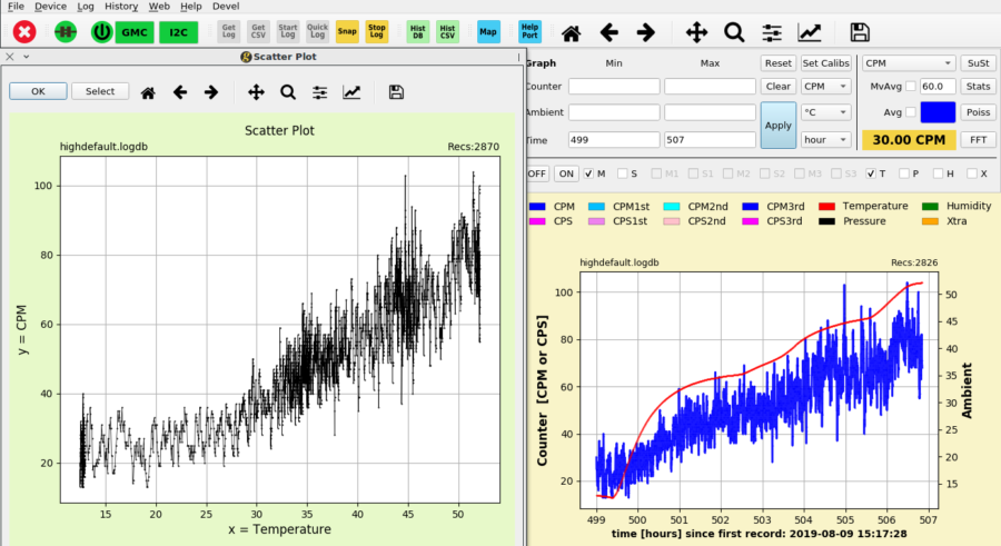
The scatterplot gives an increase from CPM=~25 ... ~36 from the room temperature range 20...30°C (68 ... 86 F).
This is quite a bit!
|
| ullix |
Posted - 04/14/2022 : 00:39:43
The temperature was noticed to have an impact e.g. in this topic: http://www.gqelectronicsllc.com/forum/topic.asp?TOPIC_ID=5481
But, read it all, at the end I realized that the tube had significant anode-overvoltage which caused the temperature sensitivity to become noticeable. Mind, you doesn't mean that there is no temp-sensitivity, only that it is not noticeable during most of normal operation.
I know I had run experiments at increased temp demonstrating a temp effect, but can't find them at the moment. But it shows what a complex system a tube is.
The good news fro your situation is that higher temp will increase the counts; if there is a light sensitivity increasing the counts, a temp sensitivity will also increase the counts, not reduce or compensate them.
Looks like you got lucky with your tube!
|
| PiR |
Posted - 04/13/2022 : 01:57:49
Hi,
quote:
Originally posted by EmfDev
@PiR, you can try to use the snow to test for UV light sensitivity.
No more snow but yesterday was a sunny day. I used a mirror to "add" more light on the tube:
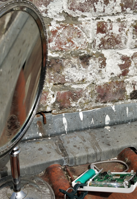
I made two 10 minutes "time counts" around noon. One with the the mirror and and one with a wood board to avoid direct sunlight on the tube:
Mirror: 36.8 average CPM
Shadow: 36.9 average CPM
Of course, other than the the wood board (about 15 cm from GMC), I tried to leave everything in the same position for the 2 counts.
My conclusion: this tube is not light sensitive. Maybe it is sensitive on the edges (cf. ullix posts), I don't know. Anyway, I would say that in "everyday use" it does not affect the CPM.
Note: in this non-scientific experiment, the temperatures of the tube/PCB/chips are supposed to have no effect. I really don't know if I can assume that, it is way off my knowledge. One can argue that the t° rise compensates the light exposure, who knows ?
Here's approximate temperatures with cheap IR cam (HTI HT-A1):
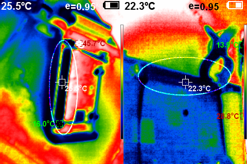
On the left, with the mirror, on the right, in the shadow. The tube is in the ellipse.
(pictures are not with same angle because of the board in the way, sorry).
Note: in IR pictures, what you see is not always what it is:for example, the white hot spots above are just light reflection, not actual t°. |
| PiR |
Posted - 04/05/2022 : 09:51:20
quote:
Originally posted by EmfDev
@PiR, you can try to use the snow to test for UV light sensitivity.
Good idea. But it melted. That's life in my hellhole country.  |
| EmfDev |
Posted - 04/04/2022 : 11:36:35
@PiR, you can try to use the snow to test for UV light sensitivity. |
| ullix |
Posted - 04/02/2022 : 23:49:52
quote:
From other nerds ;) :
h**p://www.dunorsunulab.com/
h**ps://sites.google.com/site/diygeigercounter/technical/gm-tubes-supported
rhelectronics
...
and of course, our god:
h**ps://www.gqelectronicsllc.com/comersus/store/comersus_viewItem.asp?idProduct=4530
I think you already realized yourself that your quotes do not come even close to being "Specifications"! In your first link I did not see any specs at all, in the second did you notice that they quote info which I had provided? And GQ never provided any info on where these claimed "specs" are coming from.
If you want to see an example for decent specs, look here: https://www.lndinc.com/products/geiger-mueller-tubes/712/#
Which company is even making the GQ glass tubes? Are perhaps the M and J varieties from the same company?
|
| PiR |
Posted - 04/02/2022 : 08:23:56
quote:
Originally posted by ullix
quote:
... but maybe my defective black m4011 tube drained a lot of V?
If so it would be well worth to verify!
Not really. I'm 50+ and my experience in life/work: usually, don't bother trying to understand broken things: results are not relevant. (we're not trying to land on mars).
quote:
quote:
... It's out of the tube spec.
Where did you find tube specs?
From other nerds ;) :
h**p://www.dunorsunulab.com/
h**ps://sites.google.com/site/diygeigercounter/technical/gm-tubes-supported
rhelectronics
...
and of course, our god:
h**ps://www.gqelectronicsllc.com/comersus/store/comersus_viewItem.asp?idProduct=4530
I think I know what you're trying to do: "spec are unknown ...": please, ullix, don't play like that: just say what you want to say.
Anyway: one's admit M4011 is [350-380V + 100V] (+/-15%). (400V recommended)
So, 330V is not enough.
quote:
Re Light Sensitivity: it is a bit more tricky. On some tubes you can't see a light sensitivity, no matter how hard you try. Whenever you do see light sensitivity, a "white LED" suffices; UV is not essential. But then only the inner ends of the tube seem to matter, more precisely around where the rod disappears into the glass receptacles. Fiddle a bit with the light pointing at these positions.
Thanks for the info. So if the tube is in the case and I don't see changes under the sun, I don't have to worry. That's enough info for me. I don't have to know if it would be light sensitive in other conditions.
quote:
Originally posted by Damien68
To check your setting, what you can do:
simply if you decrease the "HV Voltage" setting by 4 or 5% (set it to around 29%), wait 10 seconds for output voltage stabilisation, and if your couter continues to count around the same rate, this means that you are well on the plateau and that you can keep your initial setting (33.67%).
Thanks, I'll definitively try something like that. Although I think 29.67% = 0 CPM if I remember well.
|
| Damien68 |
Posted - 04/01/2022 : 23:28:49
quote:
Originally posted by PiR
I don't know anything about electronics, but maybe my defective black m4011 tube drained a lot of V?
It is not possible that 33.67% = +/-330V ! It's out of the tube spec.
yes it is possible that the old tube may be drawing a slight current and lowering the voltage.
To check your setting, what you can do:
simply if you decrease the "HV Voltage" setting by 4 or 5% (set it to around 29%), wait 10 seconds for output voltage stabilisation, and if your couter continues to count around the same rate, this means that you are well on the plateau and that you can keep your initial setting (33.67%). |
| ullix |
Posted - 04/01/2022 : 23:22:04
quote:
... but maybe my defective black m4011 tube drained a lot of V?
If so it would be well worth to verify!
quote:
... It's out of the tube spec.
Where did you find tube specs?
quote:
I stole a toy UV pen (sympathetic ink) from my kids..
Re Light Sensitivity: it is a bit more tricky. On some tubes you can't see a light sensitivity, no matter how hard you try. Whenever you do see light sensitivity, a "white LED" suffices; UV is not essential. But then only the inner ends of the tube seem to matter, more precisely around where the rod disappears into the glass receptacles. Fiddle a bit with the light pointing at these positions.
More snow here in Germany than in January!
|
| PiR |
Posted - 04/01/2022 : 09:09:32
quote:
Originally posted by Damien68
check anyway that your new tube is not sensitive to UV by quickly exposing it to sunlight on a sunny day (some clear tube are sensitive some others not at all).
A sunny day in Belgium ? it's snowing today! 
I stole a toy UV pen (sympathetic ink) from my kids. I don't notice a CPM rise when I light the tube. But maybe it's not the right UV (it's a toy). |
| PiR |
Posted - 04/01/2022 : 08:43:53
quote:
Originally posted by Damien68
like said PiR maybe the voltage measurements were distorted by the old defective tube.
I don't know anything about electronics, but maybe my defective black m4011 tube drained a lot of V?
It is not possible that 33.67% = +/-330V ! It's out of the tube spec.
|
| Damien68 |
Posted - 04/01/2022 : 01:50:40
like said PiR maybe the voltage measurements were distorted by the old defective tube. |
| ullix |
Posted - 04/01/2022 : 00:05:29
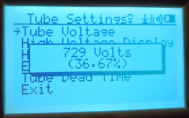
PiR, the anode voltage at 36.67% as the manufacturer's default voltage is awfully low. If your "Blue voltage" data are still valid, then this is only 337 Volt, which seemed barely enough to create counts. Yet at the moment its Poisson test is fine.
I decided to measure the Geiger Plateau curve using my CAJOE counter connected to GeigerLog via a Raspi as WiFiserver. The tube was a J305.
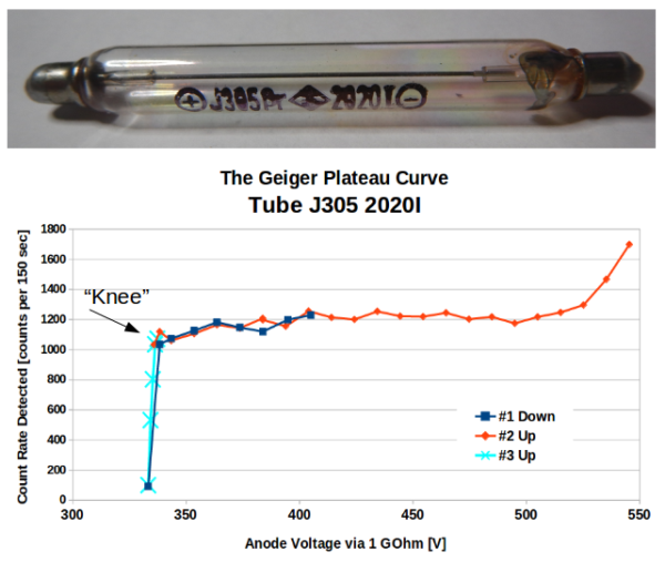
The plateau reaches from 350V to 500V. Right in the middle would be 420V, but the often used 400V is good enough.
The big surprise to me was the sharpness of the "knee". Within a single volt of anode voltage change, the count rate goes down drastically. In my data the knee is at 336V, and already sharply down at 335V.
While your and my voltages may not be comparable to the single digit, they are close. So, your 337V is surely at the brink of failure. Setting this as default by the manufacturer is clearly a mistake. Tolerances of tube, electronic components, aging, etc., may easily render some counters unusable over time!
This J305 tube is different from the M4011, but it is used in a GMC-300E+ counter, despite GQ still claiming that a M4011 is used. It is slightly smaller, and barely fits into the GMC-300E+ holder.
At a minimum one can hope that the tubes are comparable, including the anode voltages to be used. So far the "default" is a crappy setting. Set the voltage 50 ... 100V higher for a long-term reliable operation.
|
| Damien68 |
Posted - 03/31/2022 : 05:07:29
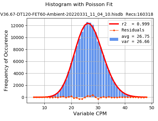
the histogram looks perfect.
check anyway that your new tube is not sensitive to UV by quickly exposing it to sunlight on a sunny day (some clear tube are sensitive some others not at all).
|
| ullix |
Posted - 03/31/2022 : 05:04:51
quote:
Maybe. but thread name is not appealing.
Then edit it to something you like better!
|
| PiR |
Posted - 03/31/2022 : 02:10:44
Hi,
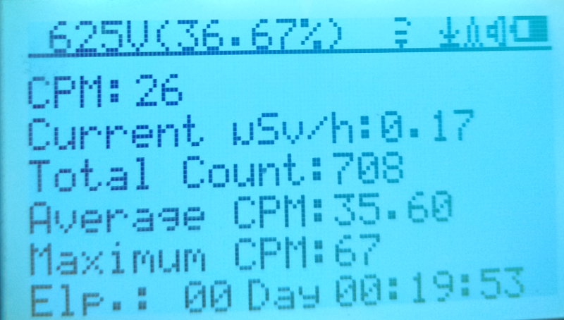
Here's a 40+ hours CPM distribution with the new tube at 36.67% (default voltage), FET at 60s, dead time 120us:
|
| PiR |
Posted - 03/29/2022 : 10:39:15
quote:
Originally posted by Damien68
the post may be of interest to other people who may be faced with the same situation.
Maybe. but thread name is not appealing.
quote:
your tubes came quickly, where did you find them?
there is a Russian tube in the lot,
Someone from Belgium on Etsy (2 business days, VERY well packed).
Other tubes are STS-5 & SI-3BG/CI-3BG (cheap).
I don't know if I'll use them. I should receive a cajoe in a few week (CN). I hope I'll feel more comfortable stuffing thing in this cheap gmc. I can't believe I didn't break my GMC-500 with all I did. |
| Damien68 |
Posted - 03/29/2022 : 10:06:43
the post may be of interest to other people who may be faced with the same situation.
your tubes came quickly, where did you find them?
there is a Russian tube in the lot, I didn't think they were still accessible and payable because of the but**er and his special OP. |
| PiR |
Posted - 03/29/2022 : 09:43:21
Hi,
New tube arrived:
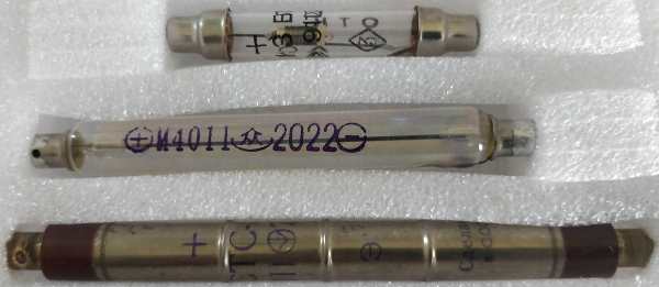
I know, I was a bit glutton ;)
In the GMC-500:
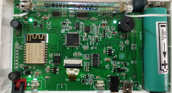
I switched tube voltage back to factory default (36.67%).
There was no click @ 29.33%.
So it seems that the old black M4011 was dead. Almost all my posts above are based on defective hardware: move me /dev/null.
I'll measure CPM distribution with GeigerLog but I don't think I'll measure another voltage on this device.
Sorry to disappoint those who wished I measure other stuff. I'm not good at that. I might end up seeing atomic drones flying around me ... ;).
I have to move on !
Thanks,
Pierre
|
| ullix |
Posted - 03/29/2022 : 07:31:25
Oh dear, too much stuff. Wayyyy too much! And a lot of crappy to very crappy Poissons!
My urgent suggestion: do NOT touch FET. Keep it at 60. Always. Do a reset and then make double sure it is at 60. Verify with GeigerLog! (menu Device->GMC->Set GMC configuration).
Another urgent one: I noticed there is a deadtime setting? Now that you say it, I remember. This is another crappy setting! Just like the FET, it may ruin the Poisson test. Switch it off and keep it there! If it has no OFF setting, then 0 (zero) should work.
Once you are finished with the current stuff, you can play with FET and Deadtime to convince yourself on their crappiness!
Thanks for the volts data. I couldn't figure out google - it just remained blank - but copied the data. I used the "blue" data.
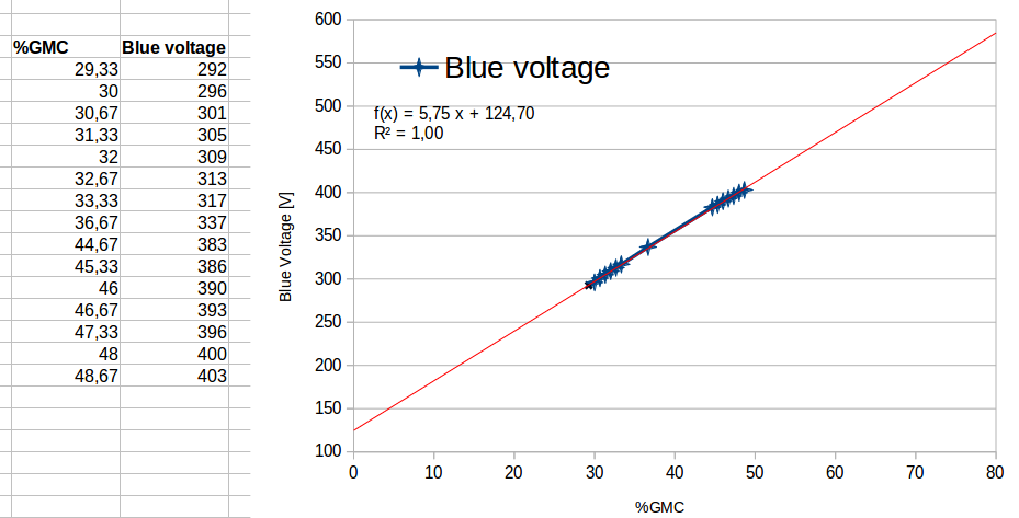
Holy Moly - this sure is linear: R2=1.00! You know I become suspicious when the data look too good. All is real?
I'd say begin with 20% and work you way up in steps of 5% (to catch the "knee") and up to 60% (450V) should not be a problem. Beyond that pay attention.
You may be the first ever to measure the Geiger curve on a M4011 ;-))
The counter has a setting of something like "Total counts" and a Reset option for this. Taking this number over fixed length intervals (10min?) suffices, Poisson not needed at this stage.
|
| PiR |
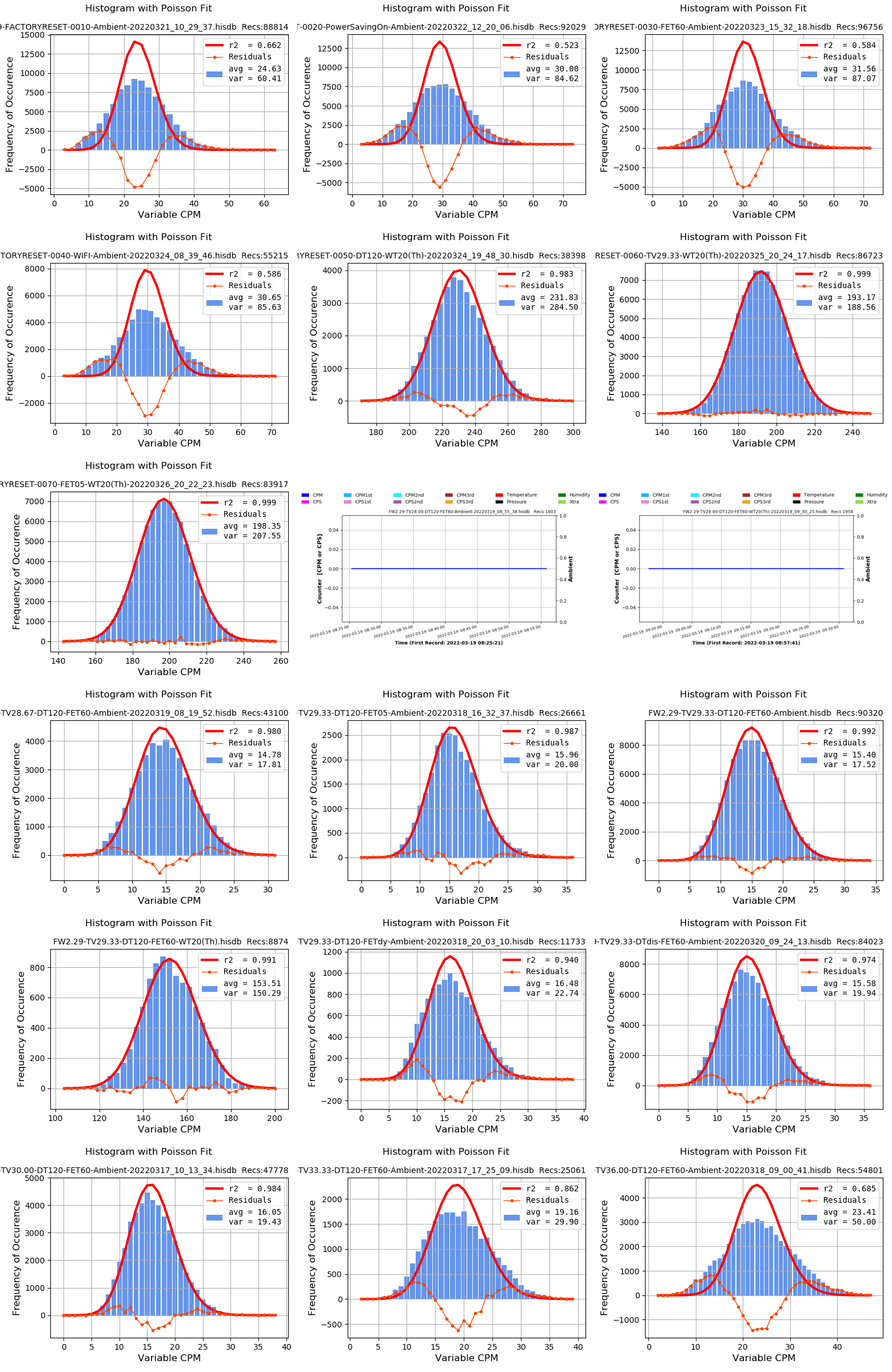
Posted - 03/29/2022 : 03:12:07
Hi,
@ullix
Here are some data computed with GeigerLog.
I mostly focus on Tube Voltage and Fast Estimation.
It is not scientific: it's just one set of measures on my GMC.
I realize now that I blinded myself about the Geiger plateau. Although I saw this cure many times, I forgot about the part before the “knee”. Sorry, big mistake; thanks ullix for showing me this curve again. So the parameters I used might be useless. Nevertheless, compiling the data is quick and so why not post them ?
Method:
begin:
Set some param -> Erase data
Wait
GQ software -> download .bin file
GeigerLog 1.30 linux -> import GMC .bin file -> crop 10 min at beginning and end -> Poiss.
End.
Filenames should (?) be self explanatory (???). Here are some abbreviations:
FW = FirmWare : Re 2.29
TV = Tube Voltage (%)
FET = Fast Estimation Time : dynamic, 05, …, 60 s
DT = tube Dead Time : disabled, 0 ? , … ? µs
Ambient = GMC just on a desk / WT20(Th) = GMC close to Thorium (WT20 TIG soldering electrodes)
USB plugged: never
Images should be in the same order following EN reading conventions.
FACTORYRESET series is after a factory reset ;). Changes from PREVIOUS measure are noted before each line:
(FW2.29, TV36.67, DTdis, FETdy, … reset your GMC and you'll now all parameters ;) )
FW2.29-FACTORYRESET-0010-Ambient-20220321_10_29_37-Poiss.png
Power saving: on
FW2.29-FACTORYRESET-0020-PowerSavingOn-Ambient-20220322_12_20_06-Poiss.png
FET dyn -> 60s
FW2.29-FACTORYRESET-0030-FET60-Ambient-20220323_15_32_18-Poiss.png
wifi + online log: on
FW2.29-FACTORYRESET-0040-WIFI-Ambient-20220324_08_39_46-Poiss.png
Thorium
alarm: off
dead time : off -> 120 µs
FW2.29-FACTORYRESET-0050-DT120-WT20(Th)-20220324_19_48_30-Poiss.png
Tube Voltage: 36.67 -> 29.33 %
FW2.29-FACTORYRESET-0060-TV29.33-WT20(Th)-20220325_20_24_17-Poiss.png
Fast Estimation Time: 60 -> 5 s
FW2.29-FACTORYRESET-0070-FET05-WT20(Th)-20220326_20_22_23-Poiss.png
This series is with Tube voltage @ 28.00 % ; too low: no click:
FW2.29-TV28.00-DT120-FET60-Ambient-20220319_08_55_38-g.png
FW2.29-TV28.00-DT120-FET60-WT20(Th)-20220319_09_30_25-g.png
This last series is with various changes. All other parameters remain unchanged and are set for my average use (power saving, accuracy display, wifi, display voltage, gyroscope, ...)
FW2.29-TV28.67-DT120-FET60-Ambient-20220319_08_19_52-Poiss.png
FW2.29-TV29.33-DT120-FET05-Ambient-20220318_16_32_37-Poiss.png
FW2.29-TV29.33-DT120-FET60-Ambient-Poiss.png
FW2.29-TV29.33-DT120-FET60-WT20(Th)-Poiss.png
FW2.29-TV29.33-DT120-FETdy-Ambient-20220318_20_03_10-Poiss.png
FW2.29-TV29.33-DTdis-FET60-Ambient-20220320_09_24_13-Poiss.png
FW2.29-TV30.00-DT120-FET60-Ambient-20220317_10_13_34-Poiss.png
FW2.29-TV33.33-DT120-FET60-Ambient-20220317_17_25_09-Poiss.png
FW2.29-TV36.00-DT120-FET60-Ambient-20220318_09_00_41-Poiss.png
|
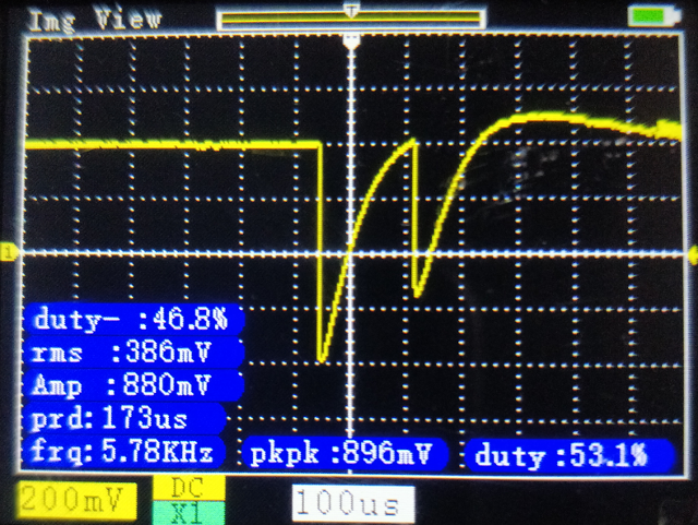
| PiR |
Posted - 03/29/2022 : 03:00:35
quote:
Originally posted by ullix
One suggestion: in your plot you have Volt vs. %GMC as a line-chart. Repeat this as a scatter plot, so we can also see how (non-)linear the dependency of setting and volt is.
Here's the .ods file:
h**ps://drive.google.com/file/d/1_V9pCGPC8ASIWXSGTwpOEOSGDzz9_Uex/view?
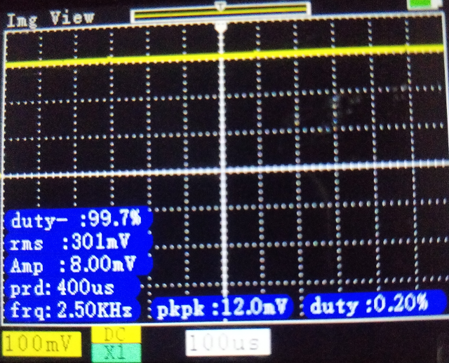
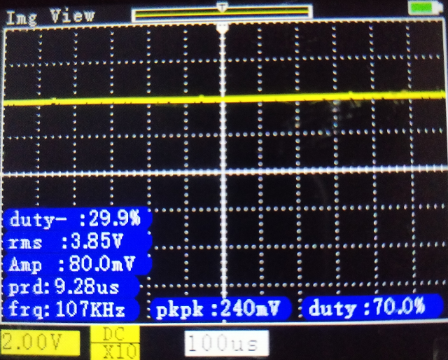
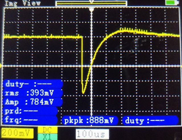
usp=sharing
quote:
The osci pics are interesting as you get rather narrow pulses. The FWHM (Full Width at Half Maximum) is only 50usec, which is only half of what I had once seen. The 2nd pic indicates that you can resolve two counts 160usec apart, which is very good, allowing a theoretical max count rate near CPS=6000 (but there are other caveats to consider...).
I forgot to mention that Dead Time was enabled and set to 120 µs.
quote:
A comment on the Geiger plateau(...)
I realize now that I blinded myself about the Geiger plateau. Although I saw this cure many times, I forgot about the part before the “knee”. Sorry, big mistake; thanks ullix for showing me this curve again.
quote:
You can actually measure the plateau yourself with the equipment in front of you. (...)
I think i'll wait for the new tube ;) |
| ullix |
Posted - 03/29/2022 : 00:12:35
Looks like it is becoming a real research project ;-)
All voltage measurements are largely consistent. At your highest setting you get something near 400V, which is what I would use for anode setting. Laboratory equipment to measure the voltage more precisely is $1000+, but it is not necessary.
One suggestion: in your plot you have Volt vs. %GMC as a line-chart. Repeat this as a scatter plot, so we can also see how (non-)linear the dependency of setting and volt is.
The osci pics are interesting as you get rather narrow pulses. The FWHM (Full Width at Half Maximum) is only 50usec, which is only half of what I had once seen. The 2nd pic indicates that you can resolve two counts 160usec apart, which is very good, allowing a theoretical max count rate near CPS=6000 (but there are other caveats to consider...).
A comment on the Geiger plateau; from Wikipedia: https://commons.wikimedia.org/wiki/File:Geiger_plateau_curve.png
The count rate measured increases with anode voltage. In the plateau the count rate still increases with voltage, but only marginally. To have the most leeway to left and right, the voltage chosen should be in the middle of this plateau, like I have drawn the 400V for the M4011 tube, which I assume(!) to be best voltage for this tube. Because this voltage is difficult to measure, you make the smallest error by trying to go right in the middle.
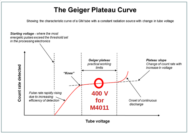
You can actually measure the plateau yourself with the equipment in front of you. Take the hottest radioactivity source you have, and measure the total counts (counts, not count rate) over a fixed period, like 10 min. Looking at your data I suggest to begin with a %GMC setting of 20%, and increase in 5% steps. Always measure the anode voltage (with the yellow DVM?). Just be careful to not go too far beyond the high end of the plateau, unless you have a spare tube at hand ;-). Your curve should kind of track the curve in the pic from left of "knee" to beign of "continuous discharge".
|
| Damien68 |
Posted - 03/28/2022 : 11:17:25
quote:
Originally posted by PiR
calibration is AUTO on this DMM.
exact that's stupid.
if the scale can't be forced, the correct input can't be measured with this method.
interesting photo, to see the rest with a new tube. |
| PiR |
Posted - 03/28/2022 : 09:39:50
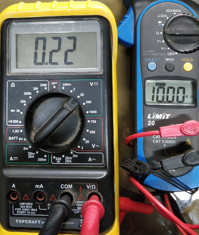
Hi,
More voltage measures with DMM and osc.
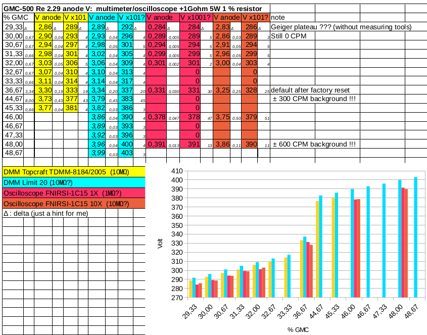
Clean table/no parasite :
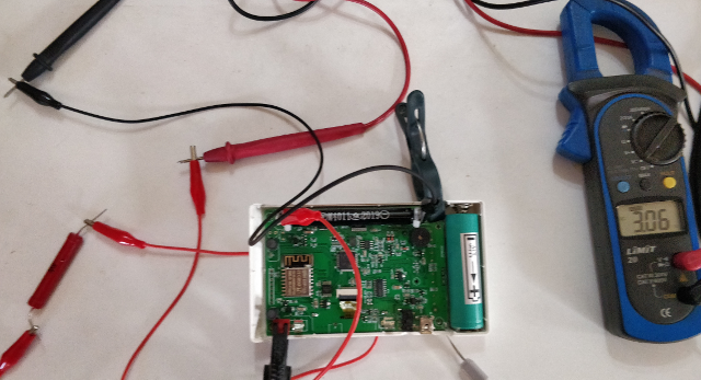
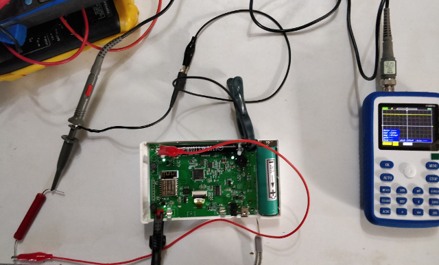
Some images of this thingy:
One click:
Two clicks:
How beautiful things I don't understand ;)
Notes:
- Some yellow (topcraft) DMM re-measured: OK in previous post.
- Blue (Limit20) is 11Mohm when I measure with other DMM but, like Damien says, it might change with scale. And calibration is AUTO on this DMM.
- I did not remove the tube, sorry Damien
- I didn't notice last time, but it looks like a few volts are lost in the measuring process: i.e. 0 CPM (lowest V in table) when those things are plugged, instead of usual ~20+ CPM background.
I suppose all this makes sense to you and is documented somewhere else. Sorry.
|
| Damien68 |
Posted - 03/28/2022 : 02:03:19
quote:
Originally posted by ullix
But when I measure the old from the new, it depends on the voltage setting of the old, and I see from 8MOhm up to > 20MOhm. However, when I measure anode voltage with either DVM via 1 GOhm, the results are close, suggesting that the "10MOhm" assumption is in fact reasonable.
@ullix:
with your old DMM, on the caliber (certainly 20v) that you use with the 1g resistance, the impedance must certainly be around 10Mohms.
with 1G and 10 Mohms it is required to multiply the voltage by (1000 + 10)/10 = 101
with 1G and 8 Mohms it is required to multiply the voltage by (1000 + 8)/8 = 126 (+25%)
I test my DMM with a second one and I found this:
@2v caliber : 11.1 Mohms
@20v caliber : 10.1 Mohms
@200v caliber : 10.0 Mohms
I corroborated the results by measuring a LiPO battery with and without an external resistance of 10.4 Mohms (measured), and check the consistency, is OK.
in most cases the DMM input will be around 10Mohms, but to be sure, it's best to check it. |
| PiR |
Posted - 03/26/2022 : 12:43:19
Hi,
Note:
Blue multimeter measuring yellow: 10.00 Mohm (picture post above);
Yellow multimeter measuring blue: 11.03 - 11.05 Mohm.
(target multimeter set to V DC)
@ullix:
The tube is a M4011 2019 black.
@Damien68:
I should receive a new 2022 M4011 (clear) soon.
If the new tube has the same behavior, then I'll try to investigate deeper.
@both
Maybe the 1 Gohm resistor I got is not that good. I cannot tell.
Maybe I got some parasite for my measures. I'm not used to do that, I'll try a "cleaner" place if needed.
and @ullix again:
As I said, I'm collecting data. Each set is usually around 24h. For different settings (mostly TV, FET, backroung vs Thorium) one at a time or combined. I'll try to post a summury when done.
The fist impression are that the best Poisson fit is (my) low voltage with high count (Th). FET does not seem that important. Maybe due 500 Re 2.29 or broken tube (but sill fitting well le Poisson). (note W10 GQ writes GMC .bin, linux GeigerLog reads .bin)
But I'll have to sort that all once finished.
Pierre
|
| Damien68 |
Posted - 03/26/2022 : 04:32:17
0.1% of 10 Mohms is 0.01Mohm
so to display 10.00 Mohms this reequire a precision of around 0.1%, with this precision, statistically more than half of the resistances will be within a range of +/- 0.05%.
10Mohms +/-0.1% remains standard (0.21€ pcs)
https://www.mouser.fr/ProductDetail/Vishay/MCA1206MD1005BP500?qs=sGAEpiMZZMtG0KNrPCHnjcm3Ue9w12BKUnSBedG0HtRNfX6NAmiMTg%3D%3D |
| Damien68 |
Posted - 03/26/2022 : 04:19:15
@PiR you could measure the 400v voltage without the tube (after removing it) to find out if it's it who is pumping the HV generator. |
| Damien68 |
Posted - 03/26/2022 : 03:58:36
the measurement method is correct:
in principle an ohmmeter applies a voltage to its terminals (here 0.22v), and measures the current which passes through the loop to determine the ratio u/i which is the resistance.
u=Ri => R=u/i
depending on how the voltmeter is made, it is possible that its impedance is not always the same and depends on the caliber selected.
anyway, the ohmmeter does not know what it is measuring, and cannot know in advance what it should display.
the problem may be that if we have rapid surges, we will not necessarily see them. |
| ullix |
Posted - 03/26/2022 : 01:55:01
Thanks to PiR it has become clear now that there was an oversight in previous discussions, in that we had seen the need for a 1% GOhm resistor, but ignored the need to know the DVM resistance to the same precision.
Now that we measure it, it comes out at 10.00 MOhm exactly? I.E at better than 0.01%? Hard to believe. I am skeptical that we can measure impedance this way. Perhaps we are applying some "electrical circle logic", and we only see the official reference?
I measured my own 2 DVMs, both specified as 10MOhm impedance. When I measure the new from the old, I also see exactly 10.00MOhm (a precision which again increases my skepticism). But when I measure the old from the new, it depends on the voltage setting of the old, and I see from 8MOhm up to > 20MOhm. However, when I measure anode voltage with either DVM via 1 GOhm, the results are close, suggesting that the "10MOhm" assumption is in fact reasonable.
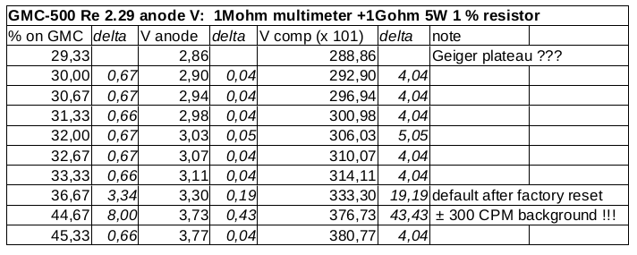
But if it is reasonable here as well, then the measurements from PiR in Reply#20 mean that the factory default is only 330V, which is too low, yet at <380V - still too low - the background is 300 CPM, suggesting that the tube is already in the continuous discharge region, firing permanently, i.e. acting as a fluorescent tube.
Leaves only the conclusion that the tube is broken. What tube was this exactly?
|
| Damien68 |
Posted - 03/25/2022 : 07:21:42
the good news is that your multimeter is actually like any other.
the bad thing is that the measurements on reply 20 are a bit low, they should be about 30% higher.
the firsts measurements make on reply 8 show the same default:
quote:
Originally posted by PiR
Here are the measures (multimeter set to 200V DC):
@ 46 % (boot default) : +/- 135-137 V
@ 29.33% (what I supposed is in the Geiger plateau) : +/- 100-101 V
From what EmfDev wrote in the topic you pinned, I should have +/- 170 V with that kind of multimeter. Or is it only for GMC-320 ? I think GMC-500 and 320 have the same M4011 tube, so I assume it should be the same voltage ?
normally it is necessary to have a tube voltage around 400v.
I suspect that there is a hardware defect.
Note: our methode measure the DC value (continuous average), maybe there are larger than normal surges/overvoltage recurents peaks.
normally there are some but very light, this is normal.
this would explain the CPM increase at a abnormal low level (300CPM @376v), and explain also the abnormal decrease of the average voltage (-30%).
it's just a suspicion. |
| PiR |
Posted - 03/25/2022 : 03:34:06
Hi again,
Just a quick update.
I don't know if it's right but here's what I just tried:
Measure the internal resistance of my multimeter (yellow, left) with another multimeter (blue, right) by stuffing the thingies in the holes:
I get 10 Mohm.
@EmfDev:
I'll try to measure the GMC tube voltage with the borrowed "blue" multimeter + 1 Gohm resistor.
Is that what you mean by "you need to find better measurements on the voltage" ?
Pierre |
| PiR |
Posted - 03/24/2022 : 23:53:54
Hi Damien68,
quote:
Originally posted by Damien68
when you make the measurements it is very important not to touch any electrical contacts with your fingers otherwise your fingers will make parasitic resistors.
Thanks for the advice.
I tried to be very careful and used alligator clips, not my hippopotamus fingers ;)
quote:
I think your multimeter must have a different impedance than what is expected and more around 7 or 8 Mohms.
It makes more sense and explains default voltage after factory reset.
I'll follow EmfDev advice and will try to find a better measuring tool .
I apologize for bothering you with stupid things made with my old cheap tools.
Pierre |
| PiR |
Posted - 03/24/2022 : 23:29:50
Hi guys,
Sorry, I edited my previous post: it is a 10 Mohm multimeter, not 1 Mohm.
I'll try to borrow another one (and the 1 Gohm resistor again).
... to be continued ...
Pierre |
| EmfDev |
Posted - 03/24/2022 : 14:35:37
Hi Pierre there might be difference in voltage but you need to find better measurements on the voltage. |
| Damien68 |
Posted - 03/24/2022 : 13:16:29
Hi Pierre,
if your multimeter has an impedance of 1Mohms you must multiply the voltage by 1001 and not by 101 but that would be too much (around 3000v).
when you make the measurements it is very important not to touch any electrical contacts with your fingers otherwise your fingers will make parasitic resistors.
I think your multimeter must have a different impedance than what is expected and more around 7 or 8 Mohms.
to check the impedance of your multimeter:
if you have a 10 Mohm resistor, you can measure the voltage of a battery with and without an external 10Mohm resistor in serie, and compare the results. |
| PiR |
Posted - 03/24/2022 : 11:35:33
Hi,
I'm still collecting data ...
But in the meantime I borrowed a 1 Gohm resistor 5W 1% (as written on paper). And here are some tube voltage measures made with my cheap multimeter:
EDIT: It is a 10 Mohm multimeter in the table belew, sorry.
I don't know what to say. The M4011 is supposed to be set around 380 V, no ? Even the factory reset voltage does not make sense to me.
What's wrong ?
The multimeter maybe ? Although the measures are quite correlated (% set in GMC and measured V).
I asked around me but I cannot find another multimeter right now.
Pierre
|
| Damien68 |
Posted - 03/17/2022 : 07:59:56
quote:
Originally posted by PiR
I don't have a "stable" source
after reading the ullix posts and docs, the only source I buy is a box of diet salt containing potassium that I poured into a thin plastic bag.
this is enough to test the counter at low levels (multiply by 2 or 3 the background level).
it can be found in some grocery stores or in drugstores.
 |
| ullix |
Posted - 03/17/2022 : 06:36:42
quote:
You should know since post #1 that I'm not equipped with that.
;-) that promises an easy life ...
quote:
I read your manual but I did not find how long a recording should last to be relevant.
Then, the best setting according to you and Poisson is when the "residuals" curve and X axis are coincident lines ?
Relevant is when your brain tells you - oh, sorry - could have told you it is relevant. This depends on what statistical "goodness" you want. Just a minute ago I posted this topic http://www.gqelectronicsllc.com/forum/topic.asp?TOPIC_ID=9836 which includes a picture showing a surprisingly well formed Poisson curve.
I didn't do anything for it, it just so happens. It is statistic of some 50000 records.
With "settings" you mean placement of the counter, and not fiddling with the settings of GeigerLog? The placement of the counter is irrelevant for statistical quality. If the quality is not good enough, just wait longer. The quality improves with square-root(counts) - with 4 times longer counting you get 2 times better quality.
In the ideal case the residuals would indeed by coincident on the x-line, but this will never happen. What you should be watching out for is that the residuals wiggle kind of randomly around the x-axis, and not in any regular pattern, like all down on the left, and all up on the right. If this were the case, I'd say something is wrong, no matter what the rest looks like.
As I said: if you want to see wrong Poissons, move the FET setting well away from 60 and record data sufficiently long. What is sufficiently long? Your brain will ... oh, we were there before.
|
| PiR |
Posted - 03/17/2022 : 05:21:24
Hi,
quote:
Originally posted by ullix
(...) you'll have to use your own brain for this!
You should know since post #1 that I'm not equipped with that.
quote:
(...) whether the recording had been stable.
I'm collecting data with various settings.
I read your manual but I did not find how long a recording should last to be relevant.
Then, the best setting according to you and Poisson is when the "residuals" curve and X axis are coincident lines ?
quote:
Ask @EmfDev.
He left this topic long ago ;)
quote:
Originally posted by Damien68
I have no friends (jock)
Lucky you!
Pierre |
| Damien68 |
Posted - 03/16/2022 : 00:32:13
quote:
Originally posted by PiR
I know: it s(t)ucks to be me ! (private joke, sorry)
it does not s(t)ucks more than to be me because it is impossible. I have no friends (joke)

 |
| ullix |
Posted - 03/16/2022 : 00:15:04
I am afraid there won't be any magic from GeigerLog; you'll have to use your own brain for this!
But its tools will be helpful. If Poisson doesn't come out right, check with Average, Moving Average, and LinFit whether the recording had been stable. If not, you may be able to select sub-sections, which are.
If you want to see how a defect Poisson looks like, set FET to 3, its "baddest" setting, and do a recording. But don't forget to set it back to 60!
You can either download the history from the counter, or log directly with GeigerLog. To understand the options, look for chapter "GMC Devices" in the manual.
quote:
Device Max CPM: 65535 (invalid if equal to 65535!)
in device extended info, should I worry doctor?
Nothing to worry, but I have no idea what it really means. Ask @EmfDev.
By the wording it should show the max count since (when?). But since the very first count should set this value, one should never see 65535 (the maximum number which can be represented with a 2 byte unsigned integer). Though most often I see 65535, and occasionally other, more reasonable, numbers.
|
| PiR |
Posted - 03/15/2022 : 10:57:41
quote:
Originally posted by ullix
Actually you do. Use Potassium as a source, (...)
A friend gave me some thorium today: WT20 TIG soldering electrodes (red tip). It is supposed to be 2% Th (and 98% W ?).
I'll have a look at that later. Right now, I'm collecting ambient data because I just installed GeigerLog.
If I understand correctly, I just have to download data from the GMC, click Poiss and your magic does the rest, ullix?
I set the GMC save mode to "every second", and the FET to max (60s).
I've gotDevice Max CPM: 65535 (invalid if equal to 65535!) in device extended info, should I worry doctor?
quote:
Originally posted by Damien68
indeed, it's stuck
I know: it s(t)ucks to be me ! (private joke, sorry)
Pierre |
| Damien68 |
Posted - 03/14/2022 : 03:55:47

indeed, it's stuck |
| ullix |
Posted - 03/14/2022 : 02:03:51
quote:
I'm not really interested in deep knowledge of the device, I don't have sufficient background; I just want my GMC-500 to work fine like when I bought it.
Too late! With these questions:
quote:
Maybe trying to correlate CPMs from GMC-500 and Terra P by hand is unrealistic ?
Maybe I should try to analyze the CPM distributions of the GMC-500 with different tube voltages ?
Maybe the M4011 tube of the GMC-500 is dead ?
Maybe I should modify the dead time ?
Maybe other ?
you are already stuck in the mud ;-))
quote:
I don't have “stable” source of radiations. I only have an Ecotest Terra P+ (SBM20 coated with thin lead, I think; a unleaded window can be opened).
Actually you do. Use Potassium as a source, which may already be in your household, read "Potty Training" from https://sourceforge.net/projects/geigerlog/files/Articles/
|
| PiR |
Posted - 03/13/2022 : 10:07:29
Hi,
Thank you all for your help.
@EmfDev
About the 2.29 FW (over 2.25) :
Thank you very much; it solved the “voltage setting loss after reboot” bug (shown in the video in previous post) which was my primary concern. So, for now, I'll stick with this it.
It does not solve the “immediate display of tube voltage change in text mode” bug. I still have to reboot the device so the display reflects the change (also shown in the video above).
Don't get me wrong: the tube voltage is changed immediately; it is just a display issue.
Anyway, the fix was very quick and this bug is not high priority for me as long as I remember it. And now I'm aware like my famous fellow citizen JCVD (https://www.youtube.com/watch?v=8ECgLA2MjFo).
I don't know if you're interested in feedback but here are issues I noticed (new from 2.03 or 2.25):
- voltage display in text mode issue discussed above
- a few minor bugs:- horizontal line in text mode while holding the device in portrait mode,
- wrong title menu (Main menu -> User option -> Alarm -> Exit: menu title is now “Alarm” instead of “User option”)
- dead time disabled by default
- useless option: motion detect: “ON backlight & displaymode” has no sense due to displaymode now using S2/S3 keys
- design mismatch:- “backlight timer” and “power saving” overlap,
- switching between option values sometimes needs S4 key and sometimes S3/S2.
Anyway, despite the above, I'm happy with FW 2.29. GQ was very responsive and I appreciate.
I would like to be noticed of FW releases for GMC-500 but I don't know how to do it.
Thanks again.
@Damien68
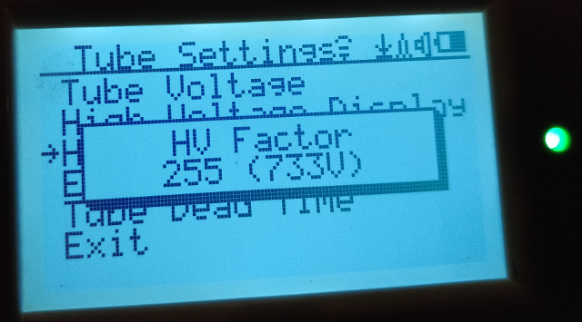
HV FACTOR: I have the GMC-500 which, if I understood you and EmfDev, is not able to measure anode voltage.
This reinforces me in the idea that the flashing from FW 2.03 to 2.25 loaded the GMC-500+ FW.
Hence, the erratic behavior.
A quick search for strings (gmc, emf, ...) in the updater (or t file) gives hints:
$ strings myserial.exe | grep -i gmc
GMC-300
GMCHistory.txt
GMC-320
GMC-500
GMC-500+
 www gmcmap.com
?Hi!!! Welcome to GMC-500+ !!! CPM = %d<br><button>LED On</button>
GMC-500
GMC-500 V1.0
 www gmcmap.com
 >HI WELCOME TO GMC500!!!
GET h**p://www gmcmap.com/log2.asp?*** HTTP/1.0
GMC520+QA
Thank you for explaining the HV factor. It might be useful if I get another GMC model in the future. Right now they are mostly out of stock or way too expensive!
Oscilloscope: I only have the 1X/10X BNC probe (button switch).
Thanks for your explanations; I don't think I will not use this tool at all.
@ullix
@Damien68
@EmfDev
I read what you write here and in some other posts. I read other materials too.
I didn't understand everything but I don't have to (like in “I don't have to understand combustion engine to drive a car”).
From all that reading, I realize that I have to read more to achieve what I (and I suppose a lot of QG GMC users) want: a CPM count that reflects abnormal conditions (of goods, construction materials, samples, ambient,...).
When I bought the GMC-500 in 2019, it seemed to me it was working out of the box. No special settings. I also had fun with it: radon balloon, https://www.lagaffe.dlvx.be/thymium/ , ...
So why am I tuning tube voltage now ?
I don't remember exactly when, I began to have the same kind of “exponential” CPM that Zygmunt (malezet) have (see ullix link above). At first, I just set the alarm higher, then switched it off, then completely switched the GMC off and forgot about it.
A few days ago, I turned it back on and read a little more on this forum. I read about Geiger plateau, and set the tube voltage to 22% on FW 2.03 (now around 30% in FW 2.29).
Then I realized FW upgrade was available if one asks for it and thought it might solve the issue.
The story then begins in post #1 of this thread (bad flash, …).
Today I realize I got a lot of things wrong and I'm not sure I already have them right.
I don't have “stable” source of radiations. I only have an Ecotest Terra P+ (SBM20 coated with thin lead, I think; a unleaded window can be opened).
Maybe trying to correlate CPMs from GMC-500 and Terra P by hand is unrealistic ?
Maybe I should try to analyze the CPM distributions of the GMC-500 with different tube voltages ?
Maybe the M4011 tube of the GMC-500 is dead ?
Maybe I should modify the dead time ?
Maybe other ?
I'm not really interested in deep knowledge of the device, I don't have sufficient background; I just want my GMC-500 to work fine like when I bought it.
Thank you again for your help.
Pierre |
| Damien68 |
Posted - 03/12/2022 : 07:07:47
about HV FACTOR:
in the new GMC500+ counter there is a small voltmeter capable of measuring the anode voltage of the tube, this with a resistance of 1Gohms an AOP and an analog input of the microcontroller.
the concern is that a resistance of 1Gohms of precision costs the price of 2 or 3 microcontroller. apparently GQ preferred to place a less expensive low precision resistor and to place a parameter to calibrate the measurement.
this parameter is HV FACTOR.
so if you decrease the HV factor the anode voltage will not change but the voltage indicated on the counter screen will be lower
your HV factor is seted to 255 maybe it's too much
about oscilloscope probe impedance:
the input impedance of an oscilloscope (on the BNC connector) is always 1Mohms.
a 10x probe divides the electrical signal by 10, inside this probe there is a resistance in series of 9Mohm which means that the impedance seen by the input of a 10x probe is 9+1 = 10Mohms.
a 1x probe does not divide the signal so there is no resistance in series on the input which means that the impedance seen by the input of a 1x probe is always 1Mohms.
for the same reasons the input impedance of a 100x probe is generally 100Mohms but some models can be made differently and have an input impedance of 10Mohms, in case of 100x probes, it is to be checked on the specifications of the probes . |
| ullix |
Posted - 03/12/2022 : 04:28:32
@Pierre: a 10MOhm DVM is plenty good; even top-top devices rarely have more. I looked at the DVM link and I and Google Lens ;-) are of the opinion it is indeed listed as 10MOhm impedance.
More helpful would be if you had a 1 Giga-Ohm resistor available. If you don't understand why this would help to get the true voltage, then read the chapter "The Anode Voltage" in this article of mine: https://sourceforge.net/projects/geigerlog/files/Articles/GeigerLog-Radiation-v1.1%28CAJOE%29-Support-v1.0.pdf/download
Perhaps your oscilloscope may become helpful: it will have come with 1 or 2 probes, and if you are lucky, one is 10MOhm, and the other higher. If one is higher, get measurement with it.
Your measured anode voltage of 136V is then rather low, and surely is not in agreement with the 700+ Volts indicated by the counter!
With my counters (300 and 500) I get 160V directly measured with a DVM, and 400V via a 1GOhm resistor (The true voltage will then be another 5-10V higher, but I mostly ignore this; for reason see article).
The intended anode voltage is 400V. This should be in the middle of the Geiger plateau, which may stretch for 30...50V to each side. https://commons.wikimedia.org/wiki/File:Geiger_plateau_curve.png
However, actual data for a M4011 tube are unknown.
Your anode voltage is not 700+ Volts; it may even be a bit too low, but don't fiddle with voltage just yet.
|
| PiR |
Posted - 03/11/2022 : 13:07:44
@ullix
Thank you for your advices.
I received a FNIRSI 1C15 Oscilloscope (https://www.fnirsi.cn/productinfo/556148.html) for Xmas but I don't know how to use it. I just smiled and said thank you ;)
I don't know if it would be useful in this case anyway.
So I took my old cheap digital multimeter (Topcraft TDMM-8184/2005 (https://www.libble.eu/topcraft-tdmm-8184/online-manual-795866/)) which is only 10 MOhm if I read well (my Flemish is even worse than my English).
Here are the measures (multimeter set to 200V DC):
@ 46 % (boot default) : +/- 135-137 V
@ 29.33% (what I supposed is in the Geiger plateau) : +/- 100-101 V
From what EmfDev wrote in the topic you pinned, I should have +/- 170 V with that kind of multimeter. Or is it only for GMC-320 ? I think GMC-500 and 320 have the same M4011 tube, so I assume it should be the same voltage ?
As I don't know anything about anything, I don't know what to thing about my low voltage setting.
About the garbage, there might be some in the data but what I meant earlier was garbage in the strings saved in the settings like "¤¦¨°°÷𬬬" …
I've got a theory:
The upgrader tool contains FW for several GMC models. Unhappily, a bug in the upgrader to 2.25 (not the FW!!) made it select the wrong FW for GMC-500 Re 2.03. Let's say, for example, it used GMC-500+or 600 FW 2.25. It could explain why the flash crashed my laptop: writing out of range (?), … And also why I had the hybrid menus, screens, … Remember that EmfDev wrote above that GMC-500 “should not be able to tell directly the Tube Voltage”.
Fortunately, the upgrader writes the FW version in the beginning of the process. So I ended up with a (corrupted) 2.25 FW.
And when I flashed again, the upgrader bug did not appear because the device was on 2.25 (not 2.03 anymore) and the correct 2.25 FW model was loaded.
Well, it's just a theory; I'm not a binwalker ;)
To conclude about the very high voltage pictures in my posts above: let's just forget them; they came from a FW that is not compatible with the device.
I'm leaving the Twilight Zone where zillions of Volts enter a GM tube to open a door to a very strange world … ;)
Thanks you all for helping.
Now I flashed FW 2.29 I just received to correct the “voltage setting loss after reboot” bug (more on that later I hope).
Pierre |
| EmfDev |
Posted - 03/11/2022 : 10:54:53
@Pierre, please re-download the link I sent you for a newer firmware. If this does not work, we can downgrade to 2.03. |
| ullix |
Posted - 03/11/2022 : 00:31:35
@Pierre,
perhaps you are right to ignore the voltage reading from the counter. However, if this is anywhere near right, you are about to burn-out your tube with the current setting of 700+ Volts!
Read this current post: http://www.gqelectronicsllc.com/forum/topic.asp?TOPIC_ID=9817
Get a DVM (Digital Volt Meter) and measure the voltage, if possible with a GigaOhm resistor. See quoted post on how to do it.
If the voltage is indeed that high, chances are all your data are garbage!
|
| PiR |
Posted - 03/10/2022 : 23:45:25
Hi EmfDev,
Thank you for taking care of this.
quote:
Originally posted by EmfDev
Not sure but it seems your device should not be able to tell directly the Tube Voltage.
Maybe. But it did. I don't know what to say. It does not do it anymore since the "clean" flash.
If found other strange pictures I took then:
I also had a setting called "HV factor" (I didn't modify it) which also disappeared now:
Anyway, you do not have to believe me. I'm not trying to convince you that it happened because I don't really care about the units: it could be Volts, percents or bananas; it's all the same to me.
This first upgrade process did not succeed (PC crashed and GMC memory was corrupted for sure (garbage in Server settings)). So everything about the state of my GMC-500 then is not relevant.
I should not have mention it. I just did it to describe accurately what happened and notice any unexpected behavior.
Let's just forget about the voltage in V.
quote:
When you do the factory reset, did you wait until the "Factory Reset" popup appears?
Yes.
GMC writes something like "factory resetting, please wait" (not sure about the words).
quote:
Also I will try to send you newer firmware for GMC500. The firmware I sent you looks like is the the latest one. I have to wait for support for the release version.
Thank you.
But maybe you could send me an older FW which does not have the "voltage lost after restart" bug; if it is possible to downgrade ?
Pierre |
| EmfDev |
Posted - 03/10/2022 : 17:05:36
Hi Pierre,
Not sure but it seems your device should not be able to tell directly the Tube Voltage. When you do the factory reset, did you wait until the "Factory Reset" popup appears?
Also I will try to send you newer firmware for GMC500. The firmware I sent you looks like is the the latest one. I have to wait for support for the release version. |
| PiR |
Posted - 03/10/2022 : 12:26:14
Hi,
Summary:
I updated my GQ GMC-500 from FW 2.03 to 2.25 with the upgrader kindly provided by EmfDev.
I first encounter a PC crash during the upgrade which corrupted the GMC memory.
I flashed again with 2.25 and now my GMC always starts the tube voltage at 46%.
First of all, I'd like to apologize: I don't know anything about anything, I am more stupid than one thinks and my English is poor, ...
Note: tube voltage:
From what I understood, I have to reduce the tube voltage on the GMC-500 to find the Geiger plateau.
I don't have a "stable" source of radiation so I use an Ecotest Terra-P+ next to the GQ GMC-500 and compare the background CPM to find the right voltage. Then I use the elctro-static "Radon" trap balloon trick to simulate peaks. I know it's not right but I think it is enough for me.
What I have:
Note: on GMC and W10, most settings are set to default or standard usage; I'll try to highlight when it's not the case (Eset IS, tube voltage, ...)
GQ GMC-500 Re 2.03
Standard mini USB cable working fine with other devices.
PC used to run the upgrader:
- poorly designed "gamer" laptop HP Omen (core i7 gen 10, 16GB DDR4, nvidia RTX 2070 8GB, NVMe SSD, Thunderbolt 3, ...) dual boot W10/linux,
- W10 Home 21H2 up to date.
- Eset IS
- no patch, crack or other strange stuff; I own all my SW (linux ...)
- main power plugged, RJ45 LAN, no other device connected.
I don't use W10 very often; I only use it for 360° video stitching or to compute images to feed VR headset (both proprietary SW). Anyway, I always update it before use.
What happened:
The laptop crashed and rebooted during the (unattended) upgrade; no other user program was running:
- connect GMC-500 to laptop : OK with W10 native drivers, recognized as USB-SERIAL CH340
- run myserial-upragder.exe
- autodetect COM: OK
- speed 1, open port: OK
Devie found on COM 6
GMC-500Re 2.03
Serial#:***
Please wait...
Good to write!
- start: OK, percents increased, I left the room when it was 2 digits % (coffee break) and when I came back, the laptop had crashed and rebooted. I'm sure of that because it was on waiting for the "BIOS" boot password. Obviously, I cannot paste the log.
There was a file named "t" (I think, it was erased by further flash) in the directory of the upgrader.
The GMC did not respond to any button pressed; I had to remove/insert the battery to be able to restart it.
At first look, the GMC seemed OK:
- FW was indeed 2.25
- date/time OK
- wifi SSID OK but password erased (or replaced by gmcmap, not sure)
- I was able to reduce the tube voltage
- BUT every value under "Server" (i.e.: URL, user ID, counter ID, ...) was filled with garbage!
What I did then:
As part of the GMC memory was corrupted, I:
- factory reset
- flash the 2.25 FW again
This time I watched closely what happened and everything was alright; no crash.
New issue:
When I change the tube voltage, the voltage shown in text mode is not modified (not really important). What is really annoying: after power on, the GMC always starts the tube voltage at 46.00% and I have to change it each time.
Something funny: after a restart, the GMC shows the previous tube voltage in text mode (although it is always 46.00% in the settings after boot).
The actual voltage applied to the tube is, I think, the one in the settings, not the one shown in text mode (CPM varies according to voltage in settings).
Here's a short video trying to show it:
https://youtu.be/_F1w-63AR5g
And now:
I flashed FW 2.25 again, factory reset the device, remove battery, … and it's still the same issue.
Another funny thing: while the GMC was on the "corrupted" FW, the text mode showed both voltage in V and %.
It's the only picture I took and kept (to remember which voltage I set) of this hybrid FW state.
Next:
If GQ wants to investigate the crash (I doubt it would be useful), I agree to try to flash FW 2.03 or other FW (GQ would need to provide it) and the 2.25 again.
I'd like to have a FW which keeps the tube voltage after reboot please.
Pierre
|
| PiR |
Posted - 03/10/2022 : 00:14:25
Hi EmfDev,
FW downloaded. Thanks.
I'll try to give feedback.
Pierre |
| EmfDev |
Posted - 03/08/2022 : 11:57:15
Hi Pierre, sent you and email. |
|
|