| Author |
 Topic Topic  |
|
|
ZLM

1271 Posts |
 Posted - 08/16/2011 : 16:54:01 Posted - 08/16/2011 : 16:54:01


|
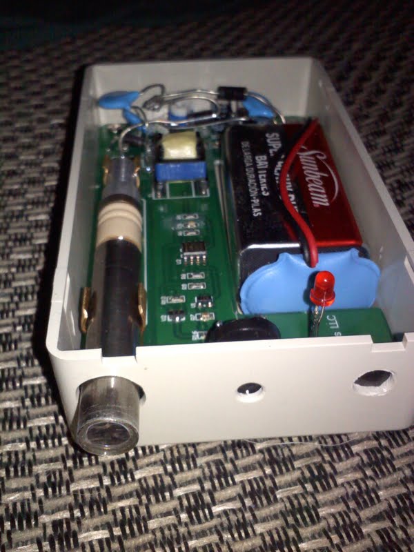
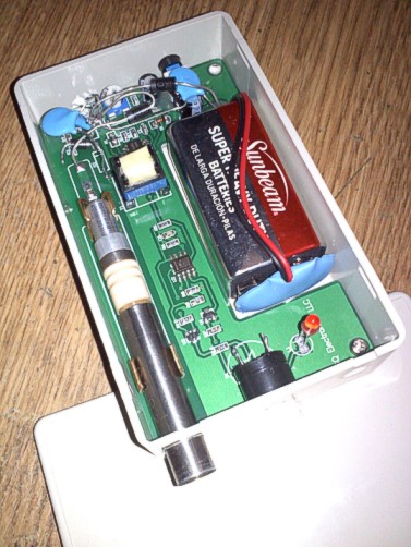
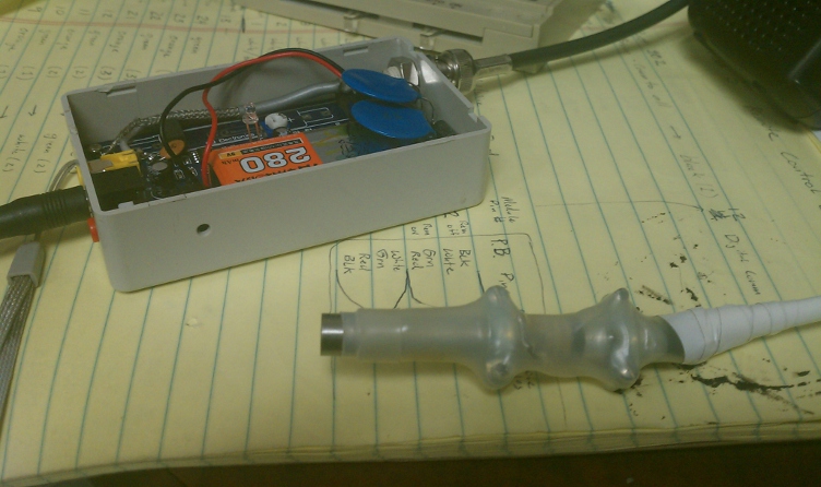
From customer Ryan:
"The end window of this 6107 just make it scream when within an inch of Am241 in open air, kinda neat how paper blocks most of the alpha particles."
The kit is GMC-060. It needs extra a voltage doubler.
For the GMC-080, it has build-in extra a voltage doubler. No voltage mode needed. The GMC-080 can adjust up to 550V tube voltage.
Image Insert:
71.72�KB
Image Insert:
68.58 KB
Image Insert:
67.94 KB |
|
| Reply #1
Odiez1

73 Posts |
Posted - 08/16/2011 : 17:24:33
|
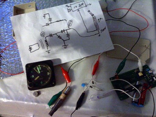
Ok, awesome schematic. :-)
2 questions.
Are those traditional rectifier diodes (1n4007) or switching?
What are the values?
Those look like ceramic non polarized, but your schematic shows ploarized caps..
Thanks much!
That's something I'd like to try. |
-Odie |
Edited by - Odiez1 on 08/16/2011 17:25:48 |
 |
|
| Reply #2
ZLM
1271 Posts |
Posted - 08/16/2011 : 17:45:36
|
I think the 1N4007 may not work well, the best diods should be high speed diods, such as UF107.
The small 0.1uf ceramic cap will work. As long as it voltage is least 800V or above. |
|
|
| Reply #3
Odiez1
73 Posts |
Posted - 08/17/2011 : 08:19:35
|
quote:
Originally posted by ZLM
I think the 1N4007 may not work well, the best diods should be high speed diods, such as UF107.
The small 0.1uf ceramic cap will work. As long as it voltage is least 800V or above.
At least they aren't FV5M-06, I can't find them...
Thank you very much. |
-Odie |
|
|
| Reply #4
Odiez1
73 Posts |
Posted - 08/21/2011 : 10:30:03
|
| Would the .001 caps and fr107 diodes from the 080 work for this configuration? |
-Odie |
|
|
| Reply #5
ZLM
1271 Posts |
Posted - 08/21/2011 : 11:07:43
|
| .001 caps is a bit small capaticity. It will work on low count, but it may not work on higher radiation count. |
|
|
| Reply #6
Odiez1
73 Posts |
Posted - 08/22/2011 : 20:44:14
|
| So, basically for the 080 we change the c3 and c7 fom 102 to 104 then bypass r3 and r4? |
-Odie |
|
|
| Reply #7
Odiez1
73 Posts |
Posted - 08/24/2011 : 09:01:55
|
quote:
Originally posted by Odiez1
So, basically for the 080 we change the c3 and c7 fom 102 to 104 then bypass r3 and r4?
Hey, I just asked this because it looks like the circuit board in the 080 is already wired from the transformer in the method you show in your schematic. It's just the values are different, less the resistors to the + connections. Am I correct on this?
Sorry to bother, but thanks for having this forum here. |
-Odie |
|
|
| Reply #8
ZLM
1271 Posts |
Posted - 08/24/2011 : 15:01:47
|
| Yes. The GMC-080 has this circuit already. His board is GMC-060. Whic is different than GMC-080. |
|
|
| Reply #9
atomic.dave
USA
65 Posts |
Posted - 08/30/2011 : 20:04:18
|
Can someone please supply a parts list and a very detailed schematic or instructions to do this mod to the 080? I can't really see what is going on in these pictures. I assume this doubling will help me with the underpowered 7616 on my 080. Sorry to ask for specifics, but I am a novice. Like if someone tells me get a 4.7k ohm resistor, I'm like huh? what watt, etc... but if I am told, get part no. 123456 from fry's, then I can handle that... Maybe I am just pushing it, but I want to get my 080 and 7616 working the way it was intended to.
quote:
Originally posted by Odiez1
Ok, awesome schematic. :-)
2 questions.
Are those traditional rectifier diodes (1n4007) or switching?
What are the values?
Those look like ceramic non polarized, but your schematic shows ploarized caps..
Thanks much!
That's something I'd like to try.
|
|
|
| Reply #10
Odiez1
73 Posts |
Posted - 08/30/2011 : 20:30:36
|
quote:
Originally posted by atomic.dave
Can someone please supply a parts list and a very detailed schematic or instructions to do this mod to the 080? I can't really see what is going on in these pictures. I assume this doubling will help me with the underpowered 7616 on my 080. Sorry to ask for specifics, but I am a novice. Like if someone tells me get a 4.7k ohm resistor, I'm like huh? what watt, etc... but if I am told, get part no. 123456 from fry's, then I can handle that... Maybe I am just pushing it, but I want to get my 080 and 7616 working the way it was intended to.
The UF107 is an "ultra fast recovery rectifying diode" rated at 800v
The 1n4007 is a traditional rectifier, but we don't need them..
It comes with an FR107, a fast recovery rectifier.
It comes down to the nano seconds of recovery time rated on the different parts.
The caps will have 104 printed on them to be .1uF. uF stands for micro farad, compared with nF or pF, nano or pico farad. It's like the metric system.
The supplied caps say 102, .001uF @ 1kV. The .1uF are the size of a quarter at 1kV.
The third digit tells the decimal places from 1 pico farad ( .0001 uF) is. So 101 is 1 pico farad (.0001 uF), 102 is 10 pico farads (.001 uF).
The voltage doubler is the part of his drawing which has the dashed lines attaching it to what the 080 already has. It looks like a full wave rectifier, but there are caps instead attached to the transformer. (capacitors pass AC voltage, block DC, but current leads voltage through a capacitor. The diodes direct positive voltage to the side with the line on the diagram, the line corresponds to the stripe on the physical component.)
So the voltage doubler brings a DC signal right from the transformer instead of an AC signal with the cap only. |
-Odie |
Edited by - Odiez1 on 08/31/2011 11:11:16 |
|
|
| Reply #11
Odiez1
73 Posts |
Posted - 08/31/2011 : 11:31:56
|
Here's some pictures of what I've done with the mods.
Image Insert:
72.12 KB
Image Insert:
168.21 KB
Image Insert:
161.18 KB |
-Odie |
Edited by - Odiez1 on 08/31/2011 11:35:27 |
|
|
| Reply #12
atomic.dave
USA
65 Posts |
Posted - 08/31/2011 : 23:59:54
|
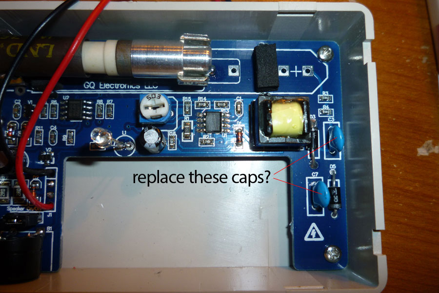
Ok, so are you saying to replace the two blue caps (C7 & C3) that are on the 080 now with two new ones that are called 104 and .1uF. And C7's replacement goes right where the old one is, but the C3 one will have one leg go to the positive of the geiger tube thus bypassing R3 & R4? Are these caps or diodes? what is the part no?
is this it?
http://www.frys.com/product/999486?site=sr:SEARCH:MAIN_RSLT_PG
quote:
Originally posted by Odiez1
quote:
Originally posted by atomic.dave
Can someone please supply a parts list and a very detailed schematic or instructions to do this mod to the 080? I can't really see what is going on in these pictures. I assume this doubling will help me with the underpowered 7616 on my 080. Sorry to ask for specifics, but I am a novice. Like if someone tells me get a 4.7k ohm resistor, I'm like huh? what watt, etc... but if I am told, get part no. 123456 from fry's, then I can handle that... Maybe I am just pushing it, but I want to get my 080 and 7616 working the way it was intended to.
The UF107 is an "ultra fast recovery rectifying diode" rated at 800v WHAT IS THIS?
The 1n4007 is a traditional rectifier, but we don't need them..
It comes with an FR107, a fast recovery rectifier.
It comes down to the nano seconds of recovery time rated on the different parts.
The caps will have 104 printed on them to be .1uF. uF stands for micro farad, compared with nF or pF, nano or pico farad. It's like the metric system.
The supplied caps say 102, .001uF @ 1kV. The .1uF are the size of a quarter at 1kV.
The third digit tells the decimal places from 1 pico farad ( .0001 uF) is. So 101 is 1 pico farad (.0001 uF), 102 is 10 pico farads (.001 uF).
The voltage doubler is the part of his drawing which has the dashed lines attaching it to what the 080 already has. It looks like a full wave rectifier, but there are caps instead attached to the transformer. (capacitors pass AC voltage, block DC, but current leads voltage through a capacitor. The diodes direct positive voltage to the side with the line on the diagram, the line corresponds to the stripe on the physical component.)
So the voltage doubler brings a DC signal right from the transformer instead of an AC signal with the cap only.
Image Insert:
122.81�KB |
|
|
| Reply #13
Odiez1
73 Posts |
Posted - 09/01/2011 : 22:11:00
|
quote:
Originally posted by atomic.dave
Ok, so are you saying to replace the two blue caps (C7 & C3) that are on the 080 now with two new ones that are called 104 and .1uF. And C7's replacement goes right where the old one is, but the C3 one will have one leg go to the positive of the geiger tube thus bypassing R3 & R4? Are these caps or diodes? what is the part no?
is this it?
h**p://www.frys.com/product/999486?site=sr:SEARCH:MAIN_RSLT_PG
The mylar ones will work. They may be thicker than the ceramic caps are.
The diodes in the unit will work, but for the voltage doubler you'll need an extra diode (same as the ones already in there) and another cap (same as the other 2 you're replacing) .
This diode is a "fast recovery rectifier" rated at 600v.
h**p://www.frys.com/product/1800447?site=sr:SEARCH:MAIN_RSLT_PG
Something like this is close to the boarder of your operating voltage. And this particular one is an SMT so it's small, and you don't want underrated components. They are prone to fail.
Is there another electronics store you can shop at? This would be better. It's what I have in mine, I replaced both of the diodes. You should do all 3 for consistency..
h**p://www.nteinc.com/specs/500to599/pdf/nte577.pdf
@ZLM Here's NTE's list of diodes.. Maybe ZLM has a better recommendation off this list?
h**p://www.nteinc.com/Web_pgs/GenPurpD_R.html
These caps would fit better, as they are ceramic discs and thinner than the mylar caps. And they are rated at 1kV.
h**p://www.nteinc.com/capacitor_web/pdf/90000.pdf |
-Odie |
Edited by - Odiez1 on 09/01/2011 23:27:28 |
|
|
| Reply #14
atomic.dave
USA
65 Posts |
Posted - 09/01/2011 : 23:03:27
|
I am so sorry to bug you again on this but I'm still not clear what I'm replacing and what needs to get done. I dint want to ruin this unit. So I need to buy one diode and three caps? And just match what's there already? Then what do i do with them? Dude this is so confusing. I'd be willing to pay you for your time to fix it... Or if you can order parts and I'll pay you. I just want it right and I'm not getting what your trying to teach me. If you can say buy this exact part and where and replace c1 with this... I still don't get it. Sorry in so dumb with this stuff but I have no clue.
The diodes in the unit will work, but for the voltage doubler you'll need an extra diode (same as the ones already in there) and another cap (same as the other 2 you're replacing) .
This diode is a "fast recovery rectifier" rated at 600v.
h**p://www.frys.com/product/1800447?site=sr:SEARCH:MAIN_RSLT_PG
Something like this is close to the boarder of your operating voltage. And this particular one is an SMT so it's small, and you don't want underrated components. They are prone to fail.
Is there another electronics store you can shop at? This would be better. It's what I have in mine, I replaced both of the diodes. You should do all 3 for consistency..
h**p://www.nteinc.com/specs/500to599/pdf/nte575.pdf
@ZLM Here's NTE's list of diodes.. Maybe ZLM has a better recommendation off this list?
h**p://www.nteinc.com/Web_pgs/GenPurpD_R.html
These caps would fit better, as they are ceramic discs and thinner than the mylar caps. And they are rated at 1kV.
h**p://www.nteinc.com/capacitor_web/pdf/90000.pdf
[/quote] |
|
|
| Reply #15
Odiez1
73 Posts |
Posted - 09/01/2011 : 23:35:28
|
It's not that hard, if you have the tools and a steady hand anything is possible.
Think of the diagram as a paper representation of the 'legs' of the components and where they connect to each other.
The triangle pointing at the stripe is a diode. They have 2 legs and the picture shows you which are which by having the stripe side (cathode?) Shown with the perpendicular short line at the triangle, 'pointing -->' to positive.
The capacitors aren't polarity specific, so the legs don't matter either way.
Basically put the new stuff in the same holes, but leave some extra leg length sticking up to work with.
Once you take it apart you'll understand how the diode for the voltage doubler goes in. Trust me.
BTW, here in Sacramento we have Metro Electronics which supplies a ton of this kind of stuff.. |
-Odie |
Edited by - Odiez1 on 09/01/2011 23:45:49 |
|
|
| Reply #16
Odiez1
73 Posts |
Posted - 09/02/2011 : 00:33:46
|
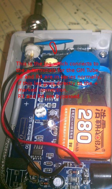
What could be better than a great picture?
Correct me if I'm worng here.
Image Insert:
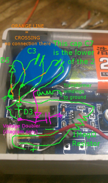
123.64 KB
Hope it makes sense.
Also, I read somewhere that the 6107 needs 1 Meg #937; anode resistance. So I put on in there where the others would be, but R3 and R4 are still out.
It seems to work pretty good, except it seems to take 2 pressings of the power switch before I hear the high voltage kick in. Then it works normally.
Before the 1M#937; I could see sparks jumping from the wire inside to the tube walls. It was cool to actually see the sparks when it "popped" near the test source, but I think for longevity it's best with the resistor and no arching..
That high voltage packs a whollop without any resistance! |
-Odie |
|
|
| Reply #17
atomic.dave
USA
65 Posts |
Posted - 09/02/2011 : 09:24:07
|
Wow, thanks for this. Excellent pic/drawing.... Still trying to digest it. I wonder why ZLM does not chime in on this. Isn't he the admin for GQ? I wish he would just say what needs to get done as I noticed he commented about one of the parts you mentioned to use and that it wasn't necessary...
quote:
Originally posted by Odiez1
What could be better than a great picture?
Correct me if I'm worng here.
Image Insert:
123.64�KB
Hope it makes sense.
Also, I read somewhere that the 6107 needs 1 Meg #937; anode resistance. So I put on in there where the others would be, but R3 and R4 are still out.
It seems to work pretty good, except it seems to take 2 pressings of the power switch before I hear the high voltage kick in. Then it works normally.
Before the 1M#937; I could see sparks jumping from the wire inside to the tube walls. It was cool to actually see the sparks when it "popped" near the test source, but I think for longevity it's best with the resistor and no arching..
That high voltage packs a whollop without any resistance!
|
|
|
| Reply #18
Odiez1
73 Posts |
Posted - 09/02/2011 : 11:01:01
|
Right. The 1n4007 isn't the right kind of diode because it can't recover from the changes fast enough.
Basically when you see a name referenced like that (1n4007, uf107, fr107, nte577 etc.), google search it for a data sheet.
All the values are listed there, find one and call your local electronics store. When you ask them what they have, they may have a similar component in stock. Then you're good to go. Sometimes finding the parts can be the hardest thing. NTE is the biggest distributer of parts around the US...outside of that?
There's Digitkey, and Mouser, and maybe even Grainger. They all have websites. |
-Odie |
Edited by - Odiez1 on 09/02/2011 11:13:05 |
|
|
| Reply #19
Odiez1
73 Posts |
Posted - 09/02/2011 : 11:45:46
|
Here's a digi-key item that might work.
h**p://search.digikey.com/script/DkSearch/dksus.dll?Detail&name=MUR4100ERLGOSCT-ND
The difference between the nte577 and this is the recovery time is 100ns, nte577 is 70ns. But what's 30 nano seconds really?
These look like the right kind of caps also.
h**p://search.digikey.com/script/DkSearch/dksus.dll?Detail&name=478-4045-ND
|
-Odie |
|
|
| Reply #20
atomic.dave
USA
65 Posts |
Posted - 09/02/2011 : 18:55:37
|
Ok, so to confirm, is this what I need to buy and install:
1. (3) NTE575 diodes
2. (1) 1M#937 resistor
3. (3) NTE 90000 series ceramic caps #104 .1uF
I'm sorry but when you are explaining this, it may make sense to you, but for me, I need a list of parts like this. Then I need to know where they go. Your drawing is kinda clear enough for me, but still I am a little unsure. Once I get the parts I'll hit you back.
Really sorry, I am sure you are getting tired of trying to help me. Thanks
quote:
Originally posted by Odiez1
Here's a digi-key item that might work.
h**p://search.digikey.com/script/DkSearch/dksus.dll?Detail&name=MUR4100ERLGOSCT-ND
The difference between the nte577 and this is the recovery time is 100ns, nte577 is 70ns. But what's 30 nano seconds really?
These look like the right kind of caps also.
h**p://search.digikey.com/script/DkSearch/dksus.dll?Detail&name=478-4045-ND
|
|
|
| Reply #21
Odiez1
73 Posts |
Posted - 09/02/2011 : 22:10:56
|
Actually no. Here's the list.
1. (3) NTE577
2. (1) 1Meg Ohm resistor The Ohm symbol came out as #937 for some reason..
3. (3) NTE 90000 series caps 104 aka .1uF at 1kV (1000 volts)
|
-Odie |
|
|
| Reply #22
Odiez1
73 Posts |
Posted - 09/02/2011 : 22:52:47
|
Let me just say, I've only replaced the original parts with the "upgraded" parts in the list. That means I only used (2) nte577 and (2) 104 @ 1kV and (1) 1M Ohm resistor at 1/2 watt.
I can't guaranty that the voltage doubler will work perfectly, but it's worth trying.
It looks like it will work, but I can't exactly say. Further I don't have an 'Americium 241' test source to test for Alpha radiation.
But mine does work with Beta and Gamma for sure, with the CDV-700 test source. |
-Odie |
|
|
| Reply #23
atomic.dave
USA
65 Posts |
Posted - 09/03/2011 : 09:24:59
|
Thanks, I'll order the parts and when they arrive, I'll be back on it. Thanks a bunch. Have a great 3 day weekend.
quote:
Originally posted by Odiez1
Let me just say, I've only replaced the original parts with the "upgraded" parts in the list. That means I only used (2) nte577 and (2) 104 @ 1kV and (1) 1M Ohm resistor at 1/2 watt.
I can't guaranty that the voltage doubler will work perfectly, but it's worth trying.
It looks like it will work, but I can't exactly say. Further I don't have an 'Americium 241' test source to test for Alpha radiation.
But mine does work with Beta and Gamma for sure, with the CDV-700 test source.
|
|
|
| Reply #24
atomic.dave
USA
65 Posts |
Posted - 09/25/2011 : 01:27:22
|
| Just got the parts today. Will get back to you soon. |
|
|
| Reply #25
wa5dxp

USA
2 Posts |
Posted - 09/25/2011 : 07:10:23
|
Can anyone tell me if you can get 750 volts out of the power supply, as that is the suggested operating voltage on the 6107 tube, and the most I can get out of my GC80 is about 560 or so.
Also, I wonder what using a voltage doubler would do to the battery life? I'm thinking of using a rechargeable 9V Lithium rechargeable which is charged externally on a special lithium charger.
The 6107 works OK, especially detecting Alpha particles, but I'm wondering if the sensitivity to other particles would improve at the specified 750V anode voltage.
Has anyone figured out a schematic for the power supply in the GC80? If so, could you post it so we can get an idea of what is going on in this thread? I'm confused, some messages say the doubler is already built into the GC80, is that correct? What voltage can you get out of yours at max? |
|
|
| Reply #26
Odiez1
73 Posts |
Posted - 09/25/2011 : 20:33:30
|
| Hey Dave, hows the project going? |
-Odie |
|
|
| Reply #27
atomic.dave
USA
65 Posts |
Posted - 09/25/2011 : 23:01:32
|
| Ok so to recap I need to replace diodes d3 and d5 and caps c3 and c7. Then bypass r3 and r4 by connecting a 1k ohm resistor to the one leg of c3 to the anode of the 7616. And that will increase voltage right? |
|
|
| Reply #28
Odiez1
73 Posts |
Posted - 09/26/2011 : 09:10:24
|
quote:
Originally posted by atomic.dave
Ok so to recap I need to replace diodes d3 and d5 and caps c3 and c7. Then bypass r3 and r4 by connecting a 1k ohm resistor to the one leg of c3 to the anode of the 7616. And that will increase voltage right?
Yup, I'm sure it will. When you're replacing C3, leave some extra leg sticking out of the hole closest to R4 so you can solder the 1M Ohm resister from the leg there to the + of the tube.
Just try to route the resistor wire as far around the yellow transformer as you can, at least 1/4" away. This will help keep unwanted magnetic interference from effecting the voltage when it's counting a lot. |
-Odie |
|
|
| Reply #29
atomic.dave
USA
65 Posts |
Posted - 09/26/2011 : 19:37:33
|
Thanks. Maybe I'll try and work on it tonight.
quote:
Originally posted by Odiez1
quote:
Originally posted by atomic.dave
Ok so to recap I need to replace diodes d3 and d5 and caps c3 and c7. Then bypass r3 and r4 by connecting a 1k ohm resistor to the one leg of c3 to the anode of the 7616. And that will increase voltage right?
Yup, I'm sure it will. When you're replacing C3, leave some extra leg sticking out of the hole closest to R4 so you can solder the 1M Ohm resister from the leg there to the + of the tube.
Just try to route the resistor wire as far around the yellow transformer as you can, at least 1/4" away. This will help keep unwanted magnetic interference from effecting the voltage when it's counting a lot.
|
|
|
| Reply #30
ENIGMA6

USA
15 Posts |
Posted - 09/27/2011 : 02:17:16
|
| DRILL BABY DRILL But do it from the underside of the board so you don't lift the solder pads off the surface. |
|
|
| Reply #31
atomic.dave
USA
65 Posts |
Posted - 09/27/2011 : 07:11:38
|
Yes but when you drill a bigger hole the pads will be eliminated. One hole I tried to make bigger seems to no longer have a pad on top. Even tried filing the lead on the diode to make it narrower but gave up last night as it got too late. I will try again. Can I email you outside this forum?
quote:
Originally posted by ENIGMA6
DRILL BABY DRILL But do it from the underside of the board so you don't lift the solder pads off the surface.
|
|
|
| Reply #32
ENIGMA6
USA
15 Posts |
Posted - 09/27/2011 : 17:54:24
|
| Dave, I must admit it takes a tiny drill bit. If the dot does come off try scraping the coating off the copper strips on the board immediately adajacent to the missing pad. Solder will bridge the gap with the lead in the hole if it isn't too far from it. And if it is an isolated pad, you can solder to the lead running to where the pad was. Good luck. |
|
|
| |
Topic |
|