| T O P I C R E V I E W |
| Stargazer 40 |
Posted - 09/21/2018 : 07:27:04
I was fortunate to obtain an early release of GQ's newest version of the 500+ GM meter - the GMC-500+V2. GQ has not only been listening and participating in the discussion about this meter here, but in the six weeks I've owned my 500+, has made numerous changes to firmware, and gone to great lengths to help us understand the circuitry and other aspects of the hardware.
The GMC-500+ is unique among commercial offerings, sporting two GM tubes of different sensitivities. It can handle background measurements and low levels of beta and gamma radiation with the more sensitive M4011 GM tube (~.1 uSv/h to 275 uSv/h), and then incident level response with a much lower sensitivity SI3BG GM tube (~100 uSv/h to 42,500 uSv/hr). Comparing with US CD-V meters, this one instrument replaces my CD-V 700 GM meter and the lower end of my CD-V 717 IC (Ion Chamber) meter.
As the 500+ has gone through evaluation on this forum, users have identified some limitations. Once these were better understood, GQ modified the firmware to add flexibility for user adjustment of how the two GM tubes interact, greatly improving the utility of the meter. Still, there were some hardware changes that were needed as well. With the release of the GMC-500+V2, two more limitations of the GMC-500+ have been eliminated or improved. And there is now an added component of DIY in the build.
Here are my two 500 meters. At the top labelled GMC-500 is my first 500+. Lower right labelled GMC-500+ is the GMC-500+V2.
Image Insert:
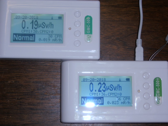
79109 bytes
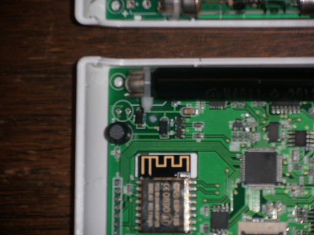
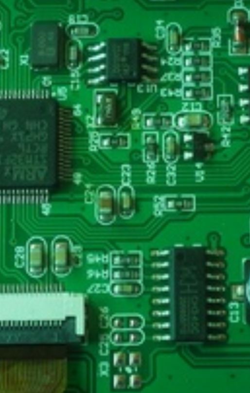
One hardware limitation of the 500+ is that both GM tubes are connected in parallel to the HV power supply. This allows response of the higher sensitivity tube to affect the response of the lower sensitivity tube. The 500+V2 eliminates that issue with a separate power supply for each tube. Here is a picture of the PCB boards with 500+ at top and 500+V2 underneath. The twin power supply sections are obvious in upper and lower left corners of the lower PCB board. The larger black components are an inductance coil for each. Missing from the 500+V2 is the pot controlling the HV voltage level to the tubes (silver component just below the upper large black component in the upper left corner of the upper PCB board). The voltage of each power supply is now controlled by firmware with new menu selections under Init Setup at the first menu level.
Image Insert:
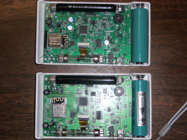
78835 bytes
Previously at the first level under Init Setup, tube selection, display and calibration items were under the Calibration menu. In the V2 there is now an additional selection titled Tube Settings.
Image Insert:
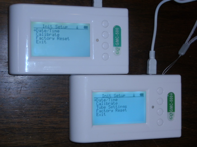
78799 bytes
Calibrate now only has the three calibration points to set. Choosing Tube Settings gives access to Selection, Display and the ability to set the voltage for each tube.
Image Insert:
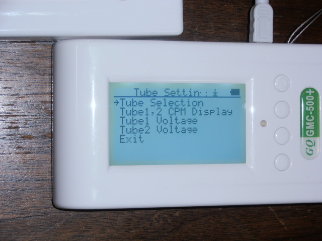
78916 bytes
When you select Tube1 or Tube2 Voltage you get a popup window with the percentage of the power supply's output. It goes away pretty fast if you don't change it but you can increase or decrease by unit count. The meter arrived with both power supplies set to 22 (22%). At these levels the power supplies each measure 392 VDC. I haven't yet tested how much change each unit increase provides, but will be one of the first things I measure when I next get some time.
That covers the first aspect of the existing hardware we were concerned about. The other was current draw and voltage drop with increased counts of most sensitive tube first and its effects on voltage at least sensitive tube. Given that we now control voltage of both power supplies with firmware (manually at present with menu adjustment of percentage), later adds to firmware may be able to adjust power supply voltage automatically as the tube draws it down due to count loading. We can also set voltage of most sensitive GM tube to 0%, effectively turning it off. Again something we've discussed as a requirement of fully utilizing each tube across its plateau area of response.
And one more optional plus to the V2. The new PCB has room to augment the primary tube power supply (M4011). Four user installed components can be added to double the current the power supply can provide. In the upper left corner of the PCB there is a parallel branch missing these components. Above the larger black component is a second spot for another inductor. The other components have already been added to this PCB (resistor, diode and a transistor as surface mount devices). When the inductor is in place the current the power supply to the primary M4011 tube is doubled.
Image Insert:
80764 bytes
We have a lot to evaluate anew. And I for one am once again pretty amazed at how an electronics company can be this responsive to user feedback. I remain committed to the belief that they intend these series of GM meters to set the standard by which other will be measured.
More to follow as I collect and present some data on how well the V2 performs .... |
| 100 L A T E S T R E P L I E S (Newest First) |
| EmfDev |
Posted - 11/14/2018 : 12:29:10
Yes the uSv is based on ullix's algorithm but it is also using the CPM which is is the result of 2 tubes being added together. But in the uSv calculation, the CPM is divided into two. So if I changed the CPM that is added together, then I'll have to modify again the uSv calculation to not assume that that the CPM is added together. That's why it's not straightforward.
The code right now doesn't automatically switch when the CPM of tube one is 90% or higher. It just caps the CPM to 1/Deadtime - 1
so that it doesn't become negative. And that's going to be a really high number anyway and will use both tube counds in the uSv calculation. |
| ikerrg |
Posted - 11/14/2018 : 11:50:04
Yes, currently the dose rate in uSv/h for the two tube mode (auto mode) is calculated using ullix�s proposed algorithm, but the CPM is still the sum of both tubes. So you need to reprogram the algorithm as I propose in replies #34 and #38 at http://www.gqelectronicsllc.com/forum/topic.asp?TOPIC_ID=5461&whichpage=1
Obviously, that requires thorough testing after implementation. In fact, now that we have the dead time of the M4011 tube set by the user, we can limit the automatic algorithm to work until 90% of the maximum CPS of the M4011 tube (0.9*1/deadtime), and then automatically switch to the other tube. In any case, even if you don�t add that switching, the result will be better than the current addition of CPMs.
|
| EmfDev |
Posted - 11/14/2018 : 11:05:59
@ikerrg, I was trying to implement this one and actually realized that the usv calculation is based from that cpm value for both tube and assumed that they were added so it's not that straightforward. Right now, I'll need more time to implement this one and then test it. So this might become available in the future. |
| ikerrg |
Posted - 11/14/2018 : 05:23:53
@EmfDev: So now that the dead time is finally implemented and seems to be working (thanks to GQ for listening to us and to Stargazer_40 for testing), the next thing is to get rid of the sum of counts when both tubes are being selected in the 500+. I already proposed how to do it in my spreadsheet, by combining the counts based on the statistical approach and the ratio of sensitivities for both tubes, but acting only on the counts, not on the dose rate in uSv/h (that is later calculated from the combined counts using the famous 0.0065 calibration of the M4011 tube). That only affects to the readings when both tubes are selected (what we called "auto" mode). It is the last remaining bit that just makes no sense in the device (to add the counts of both tubes!), and it is easily fixable in the firmware.
Well, it is the last remaining bit apart from the 3 point calibration, which is almost useless now but it makes no harm.
|
| ikerrg |
Posted - 11/12/2018 : 14:13:57
Thanks EmfDev. That information is key for ullix and GeigerLog, including the new code (55AA05). I hope this homogenizes the output of all the 4 byte firmwares not to depend on the firmware version to know how to parse the data. |
| EmfDev |
Posted - 11/12/2018 : 12:12:33
@ikerrg,
. Looks like the plane data issue is caused by the data viewer software. Someone else is working on that one.
. It's weird that 500/+ implements
0 = date time,
1 = double byte,
2 = location data,
3 = three bytes,
4 = four bytes,
but 600/+'s implementations is
0 = date time,
1 = double byte,
2 = three bytes,
3 = four bytes,
4 = location data,
will now change 600/+ implementation to same as 500/500+. This change will be included in the next firmware update. Not sure when it's going to be released.
Also in the current 500/+, if you see a 55 AA 05, that is tube type, and 00 = both, 1 = tube 1, and 2 is tube 2.
As for the medium/high threshold, we will keep it as of right now |
| ikerrg |
Posted - 11/12/2018 : 11:55:23
@EmfDev: Any comments on the "unfixed problems" I reported in reply #13?
|
| EmfDev |
Posted - 11/12/2018 : 10:15:56
@ikerrg, this will be fixed in the next firmware update so the numbers will always be multiples of 50 and with max 65000.
@Stargazer_40, we thought you didn't like that looping through the menu XD. |
| Stargazer 40 |
Posted - 11/10/2018 : 16:43:02
quote:
Originally posted by ikerrg
I have found a bug in the new firmware. It is related to the medium/high threshold setting. The setting goes up by 1000 and down by 50, so the setting has to be always a multiple of 50 (in principle). But if you go up to the upper limit of 65535, the setting jumps backwards and the number is not anymore multiple of 50. From then on, it is impossible to get back the multiples of 50 unless you reset the counter and reconfigure it again. You could fix this by setting an upper limit which is multiple of 50 (like 65000).
This can happen with all of the up arrow 10X and down arrow 1X parameter adjustments. Once you go past the top end the next placeholder to the right becomes the new digit at the bottom and you are stuck with it unless it's the least significant digit. So a cap that keeps it in the round numbers would be a good thing.
I want to thank you for fixing the menu rotation on the 600 series so that you can rotate from top to bottom or bottom to top in one button push. |
| ikerrg |
Posted - 11/10/2018 : 12:06:49
I have found a bug in the new firmware. It is related to the medium/high threshold setting. The setting goes up by 1000 and down by 50, so the setting has to be always a multiple of 50 (in principle). But if you go up to the upper limit of 65535, the setting jumps backwards and the number is not anymore multiple of 50. From then on, it is impossible to get back the multiples of 50 unless you reset the counter and reconfigure it again. You could fix this by setting an upper limit which is multiple of 50 (like 65000).
On the other hand, I miss the possibility to easily reconfigure the counter with a set of bespoke parameters after a reset or a firmware update. It is a pain having to go through all the menus to set the parameters to the desired values. Currently only the wifi configuration and the calibration is relatively easy to do, but not the dead times, the thresholds, the voltages, etc. There should be a way (e.g. in DataViewer) to export the counter configuration to a text file which can later be imported and parsed to upload the configuration, being compatible to any new firmware version because the DataViewer is doing the parsing.
|
| Stargazer 40 |
Posted - 11/09/2018 : 17:25:21
The GQ meters are doing great. Here's a pic of the 600+ as close as I can get to the infinity point on the dead time correction.
Image Insert:
457261 bytes
Dead Time is around a little more than 250. This is three times the range of the Mazur 9000. Actual CPM was 199,865CPM. I didn't get a pic of that but I will. Working with GQ on power supply check, the 7317 wouldn't go above about 230,000CPM no matter how much current was supplied. So tube had to be dead timed out. I think I am low on dead time and while GQ measured 248usec, I think that it's likely 260-265 to give a near perfect match to Mazur at the lower range limitation of the 9000 (.01-1250uSv/h).
All the meters are running the dead time/auto voltage firmware now so will make a lot of progress this weekend. |
| ikerrg |
Posted - 11/09/2018 : 15:06:55
Looking forward to seeing your results with and without the dead time correction. For 100 kCPM you should be getting quite a strong correction! |
| Stargazer 40 |
Posted - 11/09/2018 : 12:51:30
@ikerrg, I am still waiting for firmware for majority of my counters to test. I went ahead and acquired a 600+ to get a direct comparison to the Mazur 9000, and that is the first one with the new firmware. I am very pleased to report that the counts dead time corrected are right on my spreadsheet calculations AND very close match to Mazur 9000 (throughout its range), so they employ a similar approach although they do not indicate so in any of their literature. I haven't had time to do more than make a few quick tests, but I have already been really happy with results. I will present dead time correction results first and then tackle the auto voltage. I was hoping that the Medium-High reading threshold would be like the Alarm threshold with either CPM, mR/h or uSv/h, but from what you're saying it isn't. I'll check that too of course. Like you I am crunched for time at the moment. Also with more than one meter and different tubes I am looking to calibrate them all during testing to match the 600+ via the calibrated Mazur 9000. Much more to come.
|
| ikerrg |
Posted - 11/09/2018 : 10:20:34
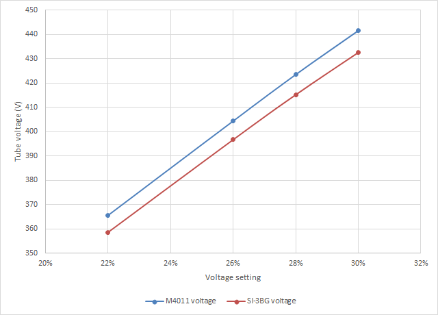
I was checking the voltages of my 500+ V2 at the different percentage settings. I got the following graph:
Image Insert:
17546 bytes
So it is a pretty linear behaviour up to 30% (about 9.5 V per each percentage increase), at least with the circuit under no load (negligible counts). Is that percentage related to the duty cycle of the switching to create the high voltage in the power supply? I suppose it will become very nonlinear above some percentage, or when the tube is under heavy count rate, which makes very difficult to estimate what is a sensible value for the auto voltage adjustment. I have set it to 2% per every 500 CPS, but I cannot test its effect.
|
| ikerrg |
Posted - 11/09/2018 : 09:56:06
I have just installed the new firmware version for the 500+ V1 (1.24) and V2 (2.02) including the dead count correction and the auto voltage adjustment. Everything that I have checked looks good so far. Sadly, for now I cannot test any of the new features for now because the maximum setting for the dead time is limited to 500 microseconds, and with that setting I would still need a strong radiation source to see a noticeable change in the count rate. Regarding the auto voltage adjustment, it is even worse, because I would need at least 500 CPS to see the effect. I am not saying that the limits for those settings are wrong, I am just saying that I do not have a radiation source strong enough to test the new firmware additions by changing the settings to the maximum values. So I think we need your strong radiation sources here, Stargazer_40! Please, do the same measurements with and without the dead time in the M4011 tube to see if the algorithm is working as expected. Check if what it is logged to the internal memory (CPS) is the corrected or the uncorrected values, as GQ may have missed that part of the code (just trying to find bugs, not blaming anyone here ;).
There are still a couple of unfixed problems (not completely firmware related) that we reported some time ago:
-The conversion to .csv in the DataViewer 2.54 software has been failing the last times I have tested it (see my posts about the measurements in planes, e.g. http://www.gqelectronicsllc.com/forum/topic.asp?TOPIC_ID=5416 , reply #37). Have you found the reason of the problem?
-It might be related to the previous: have you fixed what ullix said about the 55 AA 02 code being used for �Note/Location text� which was changed to define a �triple data byte� in the new 4 byte firmwares? All the discussion is in http://www.gqelectronicsllc.com/forum/topic.asp?TOPIC_ID=5331 , starting at reply #41. That could be causing the problem in DataViewer when interpreting high CPM/CPS counts.
And to finish, I would like to say that the CPM threshold for medium and high radiation level indications are defined for both tubes at once. It is just a cosmetic thing that I do not pay too much attention to, but it should be possible to set some different values for both tubes independently, or set the values in uSv/h (so the adequate conversion for each tube is already included). At present, if you select the low sensitivity tube, you should also change those thresholds so their values make sense.
|
| donghelan |
Posted - 11/08/2018 : 16:35:53
quote:
Originally posted by Stargazer 40
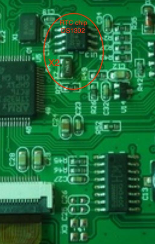
Here is fuzzy pic of closeup of Xtal areas. X2 in your image if there is on other side of board? Here obviously is an X2 component soldered in.
Image Insert:
52199 bytes
Note that this is 500+V1.
Thanks again, Stargazer 40 for helping me pin pointing the problem with an incomplete "Monday morning" Geiger counter
|
| donghelan |
Posted - 11/07/2018 : 16:11:13
Cool! Thanx it is missing! See my high resolution picture in the fore mentioned thread  |
| Stargazer 40 |
Posted - 11/07/2018 : 15:58:52
Here is fuzzy pic of closeup of Xtal areas. X2 in your image if there is on other side of board? Here obviously is an X2 component soldered in.
Image Insert:
49180 bytes
Note that this is 500+V1. |
| donghelan |
Posted - 11/07/2018 : 15:41:15
@Stargazer 40,
can you zoom in on the RTC of this unit in higher resolution? My GMC-500+ RTC does not function, maybe X-tal forgotten or loose.
see my other thread on this subject: "GMC-500+ RTC HW or FW issue? " |
| ikerrg |
Posted - 11/07/2018 : 14:03:49
I do not complain anyway. I will test any new functionality as far as I can.
I have just ordered some smoke detectors to create a �powerful� unidirectional gamma point source totally enclosed in lead but on one side. I plan to be able to finally characterize the sensitivity of both the M4011 and the SI-3BG to low energy gammas (about 60 keV), and find their sensitivity ratio. I have already checked that both tubes can detect those low energy gammas with only one Americium-241 pellet. I also want to probe that the tubes have different sensitivities to different energy gammas, and the Americium is perfect because it almost acts as a monochromatic gamma source, so I expect a different ratio that the one ullix found in his experiments with potassium-40 (1.4 MeV gammas). The higher energy gammas should pass unnoticed through the tubes much easily than the lower energy gammas, which interact more with matter and create secondary electrons in the metal of the tube that produce the avalanche effect. More to come in the following weeks.
|
| EmfDev |
Posted - 11/07/2018 : 10:05:11
@ikerrg, you will most likely receive a firmware with auto voltage adjustment with configurable medium/high threshold. |
| ZLM |
Posted - 11/06/2018 : 11:14:37
Still under testing. Will be very soon. |
| ikerrg |
Posted - 11/06/2018 : 10:57:35
@EmfDev: Do you know anything new about the firmware update that includes the deadtime correction? From my point of view, you do not need to add any voltage correction for now (it is better to do the changes in single steps), so the firmware should be ready. Are you finding unexpected problems when implementing the algorithm? |
| EmfDev |
Posted - 11/05/2018 : 17:25:03
@Stargazer_40, that seems to be from the old version of hardware. I'll have to check the new schematic,
will update later. |
| Stargazer 40 |
Posted - 11/04/2018 : 05:21:42
quote:
Originally posted by ullix
Before you get overly excited about my little scope, some warning on its limitation. The bandwidth is plenty good for all Geiger work, that is of no concern.
The input impedance, however, is only 1MOhm, and the voltage limit is +/- 40V only! Don't touch the HV with it!
Not nice, but one can live with it; just keep this in mind when you interpret your signals!
Thanks ullix, the limitations are clearly presented in the US version as well. The compensation thing is also understood. I would use existing BNC 1-10X probes and add BNC to MCX converters to plug into scope. At this point I am still trying to understand GQ's choice of test points in the power supply circuit as their displays seem to eliminate the ambiguity of the dead time measure. |
| Stargazer 40 |
Posted - 11/04/2018 : 05:13:58
quote:
Originally posted by EmfDev
Tube 1, is from ground and the collector of transistor V3. And ground to collector of transistor V4 for tube 2.
Are V3 and V4 in same circuit location as V5 in this picture you posted to ullix's 500+ review thread?
Image Insert:
39063 bytes |
| ullix |
Posted - 11/04/2018 : 05:11:55
Before you get overly excited about my little scope, some warning on its limitation. The bandwidth is plenty good for all Geiger work, that is of no concern.
The input impedance, however, is only 1MOhm, and the voltage limit is +/- 40V only! Don't touch the HV with it!
But you need probes anyway (only one 1x probe is included) and with 2 probes like this https://www.amazon.de/gp/product/B01N8TFP8T/ref=od_aui_detailpages00?ie=UTF8&psc=1 you get 10MOhm input impedance (i.e. an impedance like your DVM has) and a 600V pp limit. So, you can touch your anode with the probe.
The disadvantage is that the probes cannot be compensated, neither at the probe nor at the scope. Using the built-in signal generator (also very helpful, with the much better Hantek scope you still get no signal generator!) and the 2 probes connected to it in 1x and 10x mode, you see the signal's distortion in 10x mode - but not in 1x mode - in the picture. (The yellow trace is 1x mode, I forgot to change the setting in the scope; it is not auto-detected).
Image Insert:
38912 bytes
Not nice, but one can live with it; just keep this in mind when you interpret your signals!
|
| donghelan |
Posted - 11/03/2018 : 08:00:28
When more precision, stability and software flexibility is required, it comes with significant higher (EU) price tag from Friesland (NL), but still it beats tektronics :)
https://www.tiepie.com/en/usb-oscilloscope |
| Stargazer 40 |
Posted - 11/03/2018 : 06:50:13
Actually like the upgrade to SainSmart(same scope with slightly different name in US) 212 with the touch screen. Get the armored rubber case and stand and I REALLY like the little micro BNC connectors. $110USD and $13USD for the case. Would use existing probes with converters from BNC to micro BNC.
https://www.amazon.com/dp/B074QBQNB7/ref=biss_dp_t_asn |
| donghelan |
Posted - 11/03/2018 : 06:34:06
This amazing software SpecLab by HAMmer Wolfgang Buescher is able to analyze sound output from Geiger counters on your sound port as well when you are on a low budget ;)
https://www.qsl.net/dl4yhf/spectra1.html |
| donghelan |
Posted - 11/03/2018 : 06:26:56
This Hantek is of course from China too, suitable till 200MHz, amazing stuff and inspiring thread :)
https://www.circuitspecialists.com/hantek-200mhz-digital-storage-oscilloscope-dso5202p.html |
| donghelan |
Posted - 11/03/2018 : 06:15:14
@Stargazer 40, the mini scopes are really amazing. inclined to buy here in Japan one of these to replace the sound input ports of my PC ;).
And no problem they are all English :)
same one as Ullix has, SignSmart DSO202 in Japan:
https://www.amazon.co.jp/gp/product/B00SXVUETU/ref=s9_dcacsd_dcoop_bw_c_x_1_w
or this higher spec4 channel SignSonic DSO203 (sorry lots of double byte characters from Amazon Japan ):
https://www.amazon.co.jp/DSO203-%E3%83%87%E3%82%B8%E3%82%BF%E3%83%AB%E3%82%AA%E3%82%B7%E3%83%AD%E3%82%B9%E3%82%B3%E3%83%BC%E3%83%97-%E3%83%9F%E3%83%8B%E3%82%AD%E3%83%83%E3%83%88-72MHz-%E3%83%A1%E3%82%BF%E3%83%AB%E3%82%B7%E3%82%A7%E3%83%AB/dp/B005SQOWSW/ |
| Stargazer 40 |
Posted - 11/03/2018 : 04:35:39
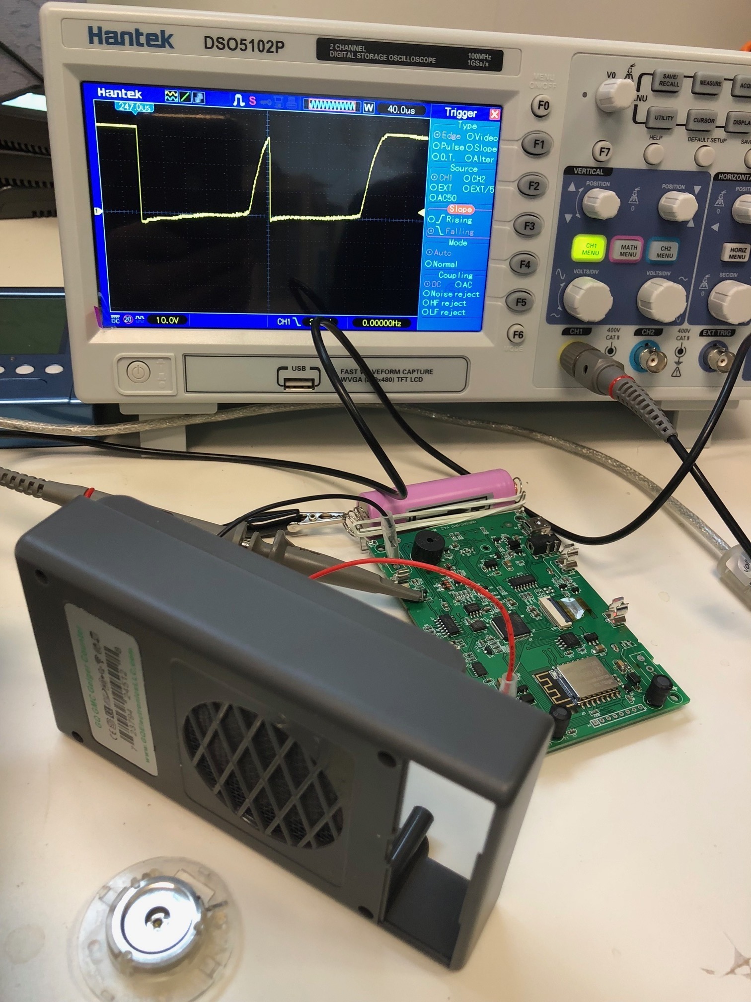
@ullix, I had read through that entire thread before. Amazing to me the capability of modern oscilloscopes. In the 1970's I built two Heathkit oscilloscopes. They were quite capable and one was a dual trace. Long gone now and I picked up this Heath from an estate sale years ago when buying some ham radios. To see the little, almost smartphone-like scope with what it can do and the Hantek that GQ is using and what they seem to be able to do so effortlessly, so very cool.
So the real question is what the counter actually counts. Some threshold needs to be counted and you're saying if there is an audio tic indicating that the counter is counting and close enough together gets you dead time. I think in the diagram above we're talking about the Resolving time and not the Recovery time. When the pulse falls below the detection limit it will generate a count. I am still interested in GQ's measure because it is more black and white/on and off. And on the graph above, what appears to not be very sensitive effect dead time-wise is also plotted on semi log graph. When we are talking about what upper-end effects of deadtime limiting tube response and get to the infinity point and turn negative from calculation we can estimate simply from actual response with high enough activity source. We are almost seeing that with the very sensitive 7317 and SBT-11A tubes now. Power supply issues appear to be behind us and we are actually seeing that we can just get so much out of some of these tubes before they will go no higher. It is at those measures that the dead time correction is especially important.
The article I posted link to is dated 1949. Definitions likely have evolved and dead time may now include through end of Recovery period. It isn't described that way though in any web search result. And people I've chatted with call the later effect 'latency'. Still, just because voltage is increasing to what it was before pulse, doesn't mean the tube is ready to indicate pulse again. That is gyst of point I was making, so my plots above are pretty worthless unless as you say multiple pulses come in close together. My scope isn't a storage scope. All I see is a bunch of overlain pulses from common trigger point (very active sources for tube tested). I'll look at English varient of the scope you referenced. And the one GQ is using. Thanks for thoughts.
|
| ullix |
Posted - 11/03/2018 : 02:50:15
It is not so difficult to measure the "Resolve" time. All you need is a 2-channel storage oscilloscope; a simple but sufficient one is this: https://www.amazon.de/gp/product/B00SXVUETU/ref=oh_aui_search_detailpage?ie=UTF8&psc=1
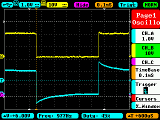
Look into my measurements shown here http://www.gqelectronicsllc.com/forum/topic.asp?TOPIC_ID=4598 under Reply #14.You see dual traces of anode signal and audio signal. The bottom 2 pics are most relevant.
You see that @100�s there is no audio signal, while @150�s there is. Now, this is using the audio signal as a proxy for a "good" count, which needs to be proven to be true.
With this and other measurements I concluded back then that the "deadtime" - you now call it "resolve time" - was 200�s. This time would be used for the "deadtime-correction" with the formula I gave.
For new measurements I'd suggest to use channel 1 at the cathode (not anode, because the counter uses cathode sensing), and make this the trigger signal, and use channel 2 at the interrupt pin of the microprocessor, which is used for counting.
And then use a high-count source and restart single osci shots until you have some where 2 pulses come in close enough succession from 50�s ... 500�s. Is a bit cumbersome but possible.
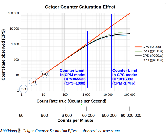
Bear in mind that it is not overly critical what the exact deadtime/resolve time is, as shown in this graph:
Image Insert:
92306 bytes |
| Stargazer 40 |
Posted - 11/02/2018 : 15:44:14
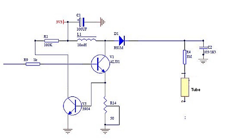
I don't believe that it is sufficient for the voltage drop to return to the level prior to the particle caused avalanche for determination of dead time. This paper from 1949 discusses further delay while positive particles redistribute within the GM tube. It is not simply a function of power supply's ability to support with enough current.
https://nvlpubs.nist.gov/nistpubs/jres/42/jresv42n3p241_A1b.pdf
Here is figure eight
Image Insert:
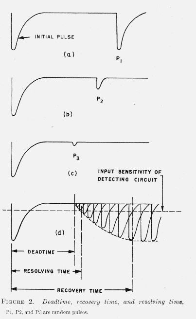
28626 bytes
The GM tube won't be fully ready till Recovery Time complete, but probably will generate a pulse at Resolving Time. @GQ, what does your measure at the Collector of the transistor actually mean? It doesn't look like the pulses we've seen so far. |
| Stargazer 40 |
Posted - 11/02/2018 : 11:51:14
I think it's important to test both of these utilities. I have already forwards serials for updates. Please include auto voltage and dead time correction.
I have been attempting to contact LND and chat with their sales tech guy. Turns out he is the owner and so far has not been available. Will keep trying but so far, nada.
|
| EmfDev |
Posted - 11/02/2018 : 09:50:19
@ikerrg, Stargazer40,
It's possible to implement a power supply that can maintain the same voltage but the main concern is the cost so for now, we'll try to avoid it. For now, we'll just fix the dead time to those values as before and see what happens. For the auto voltage regulation,
I'll put in 0-5% increase every 500 in last 3 CPS and I'll let you guys test/decide only if you want to. |
| Stargazer 40 |
Posted - 11/02/2018 : 06:39:26
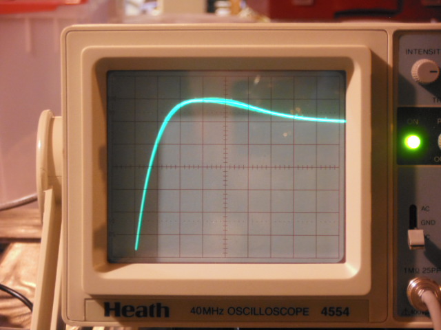
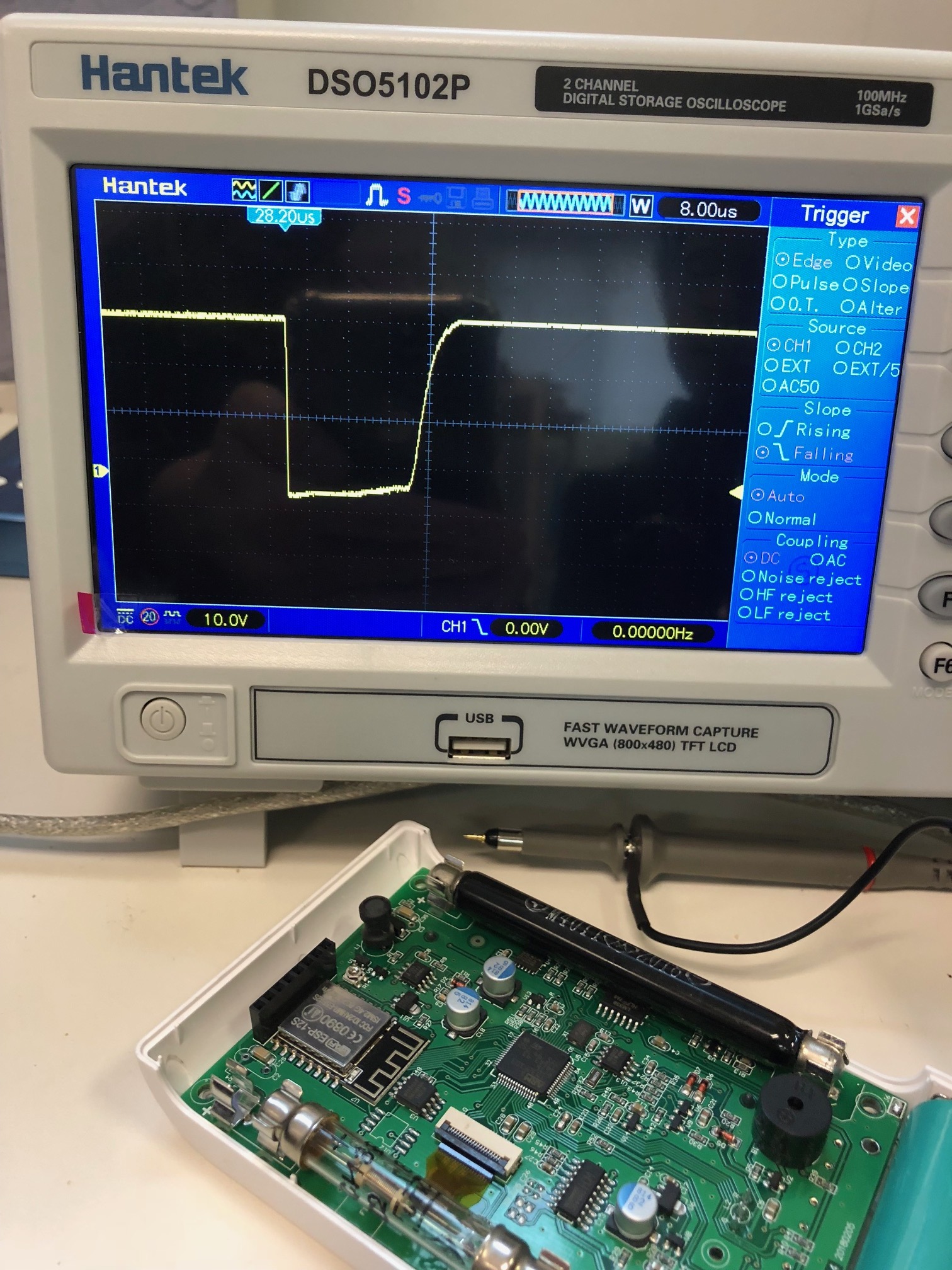
Next I did the SBT-11A at 450VDC. Here is 100usec per major division. With mantles.
Image Insert:
78663 bytes
I tried to measure the LND-712 that I adapted to the 500+V1. It has a 10Mohm anode resistor in the wand and the LND-712 is glued to the tube so can't get at it to get past it to just the anode. I could see very small voltage drops at the meter connection to the wand cable, but couldn't get low enough trigger to get pulse locked in on the display. |
| Stargazer 40 |
Posted - 11/02/2018 : 05:07:22
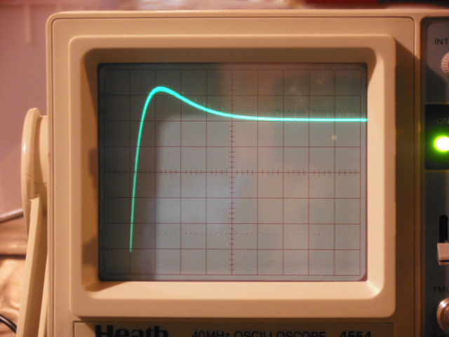
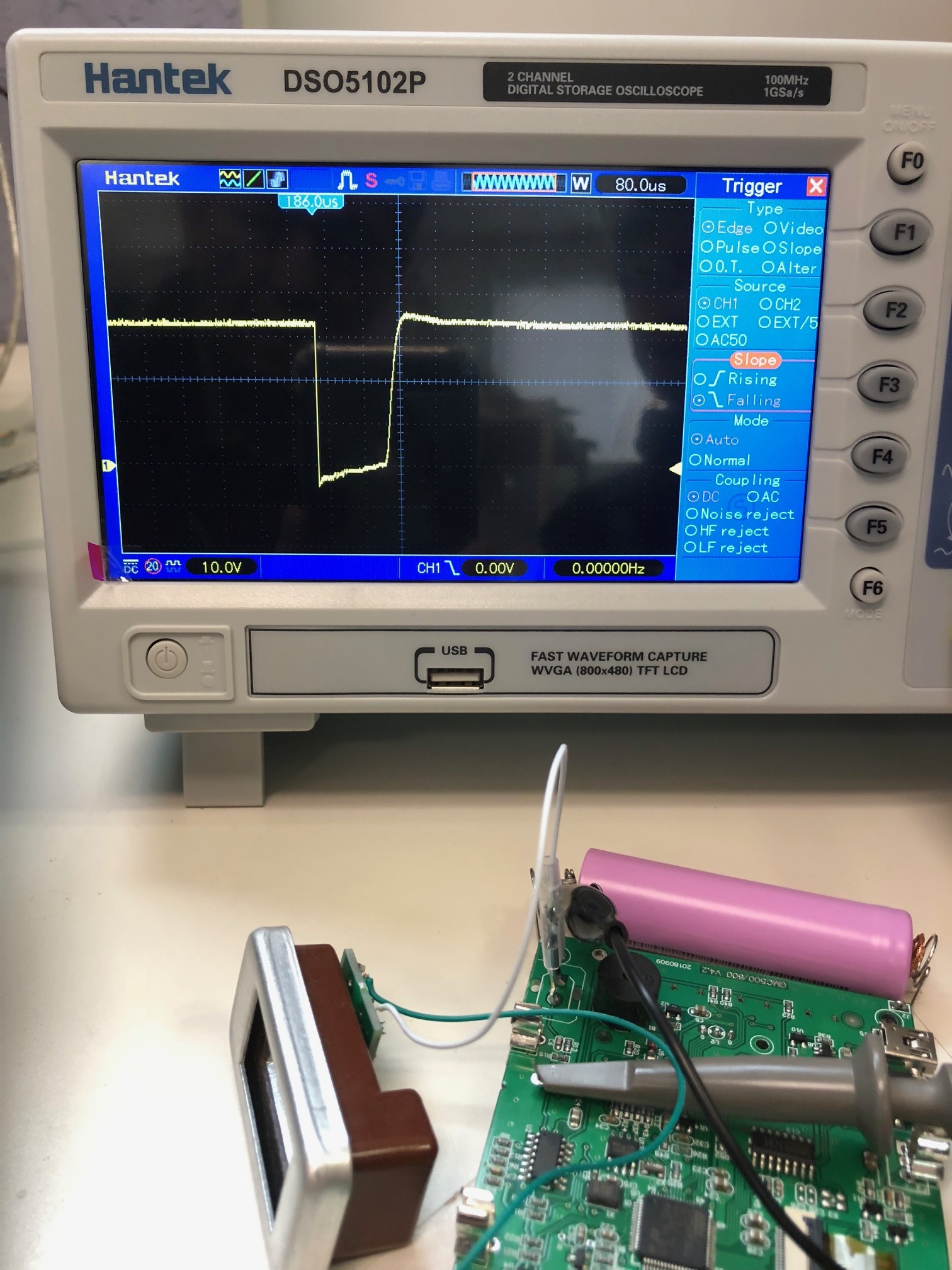
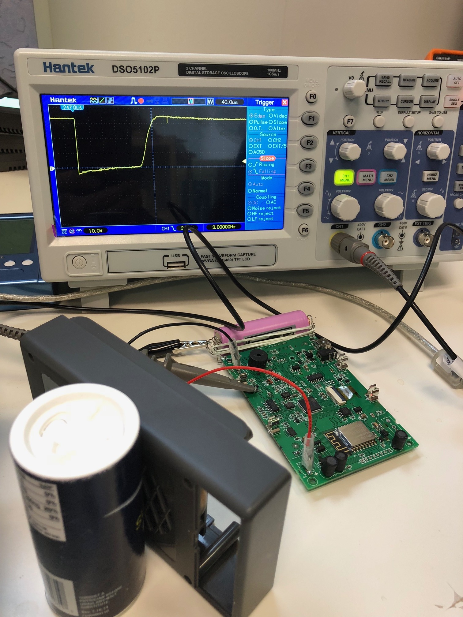
My oscilloscope is a bit dated, but the functionality is there. Testing the M4011 with voltage set at 450VDC with 1G probe in series and gas mantles. Connections are (-) battery clip and anode clip (after anode resistor). Here is a shot of the screen (I will get better at this) with vertical .5VDC and horizontal 50usec per large division. I can see recovery, but aside from voltage settling only the quicker settling between tubes is indicative of smaller deadtimes.
Image Insert:
80950 bytes
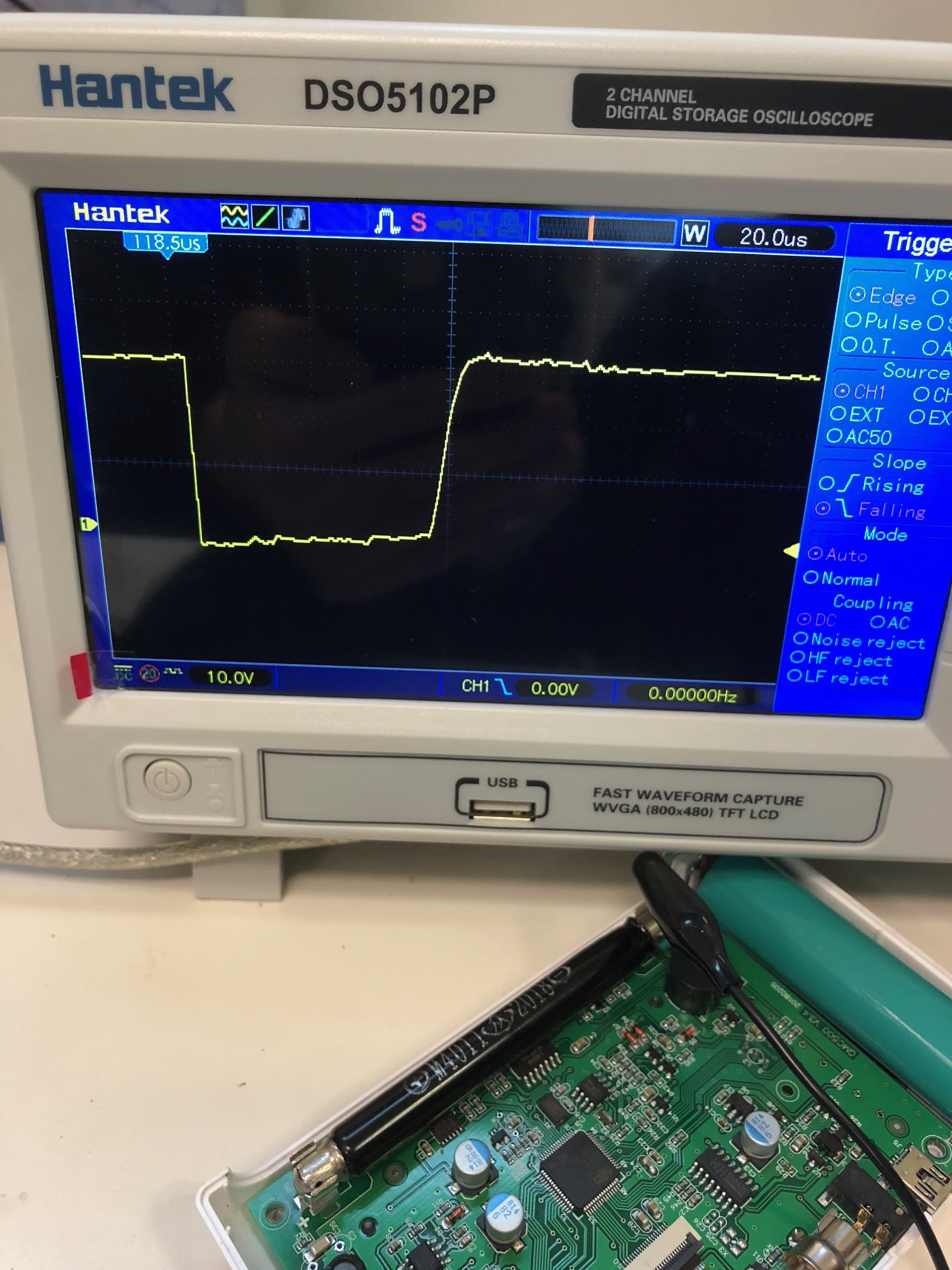
And here is SI3BG with 50usec. Faster recovery from power supply response.
Image Insert:
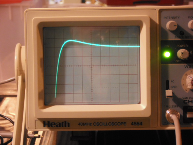
81166 bytes
|
| ikerrg |
Posted - 11/02/2018 : 01:08:59
@EmfDev: That is an interesting finding! And it makes sense. The avalanche event takes longer to extinguish when the voltage is higher, basically because the amount of charge flowing (current) is also larger. But it is good news, as the short dead time is only needed when the CPM is high, which for the present HV PS (not auto regulated) corresponds to when the voltage is smaller in the tubes.
All these effects are difficult to take into account accurately in the firmware (a full characterization of each manufactured tube would be required). The firmware will need to store a voltage vs. dead time curve + be able to read the PS voltage to set the correct dead time correction at each voltage.
Alternatively (and I think this is the best thing to do), the PS could just keep the voltage at the same value just at the low end of the plateau (350 V for the M4011), resulting in the shortest dead time (constant) and a longer life time for the tube. This is easier, but it will require a new hardware revision to control the voltage of the PS. But it is a win win situation, because it will remove also the dependence on the working point in the slope of the plateau, so the sensitivity of the tube will be constant at any CPM or radiation level.
So, in summary, with the addition of the dead time correction to the firmware (only a single constant dead time), if you also add later a voltage control system to keep the voltage steady at any count rate (obviously up to a maximum defined threshold), you will have a measurement accuracy unrivalled in any consumer device. The GM counters could be even certified by calibration laboratories! |
| EmfDev |
Posted - 11/01/2018 : 16:06:35
Tube 1, is from ground and the collector of transistor V3. And ground to collector of transistor V4 for tube 2.
Some interesting findings for M4011. We tried to measure the dead time by varying to voltage and observed that
the dead time becomes narrower or shorter (66 micro seconds with ~350V) compared to the 120 uS with around 400V.
Does that mean that the minimum dead time from the LND 7317 of 40uS can be reached at very high CPM when the voltage
drops really low? We'll need more testing for this one. |
| Stargazer 40 |
Posted - 11/01/2018 : 15:50:25
@EmfDef, what two points on the board are you taking measurements from? |
| EmfDev |
Posted - 11/01/2018 : 15:47:54
@ikerrg, for the SI-3BG, we used the smoke detector/gamma to help produce a count. |
| EmfDev |
Posted - 11/01/2018 : 15:45:17
This one is for the SBT-11 tube. It's around 180-200 uS.
SBT-11 using alpha/gamma
609541 bytes |
| Stargazer 40 |
Posted - 11/01/2018 : 15:11:55
@ikerrg, you are certainly right. The dead time correction down at 30usec takes us comfortably past 50 R/hr with the SI3BG (20-25% add to CPM). First Responder turn around point is between 35-55 R/hr (300-500mSv/h). Mild Radiation Sickness occurs at roughly 3.5-4 times that upper limit (1,750mSv/h). No other personal dosimeter gets anywhere close to being able to take readings at that level. Makes the 500+ absolutely unique in its applicability. |
| ikerrg |
Posted - 11/01/2018 : 14:54:44
That is awesome! So the M4011 is actually a quick tube, and that number matches perfectly to what we guessed from user06 measurements. Regarding the SI-3BG, even if it does not matter too much, the evidence is the evidence! Great tube to measure extremely high radiation. I wonder if that short dead time will be the same in higher fields. What source did you use to measure the SI-3BG? Was it just a background event? |
| Stargazer 40 |
Posted - 11/01/2018 : 14:28:42
Very interesting indeed! I have been trying to reach tech support at LND to talk about their tubes and dead time and still waiting for call back. What about the SBT-11/11A?
The SI3BG probably isn't all that important. If the tube ever gets to the point where dead time is important for conversion, no one would want to be there to witness. |
| EmfDev |
Posted - 11/01/2018 : 14:07:53
These are for the 500/+ tubes.
M4011 = 120 uS
SI-3BG = 30 uS. (very different from the specifications minimum of 190 uS)
M4011
657811 bytes
SI-3BG
724945 bytes |
| EmfDev |
Posted - 11/01/2018 : 13:42:56
We just found that the 600+ LND 7317 dead time is on average about 240 microseconds.
Gamma
671843 bytes
Alpha
667953 bytes |
| ikerrg |
Posted - 11/01/2018 : 09:01:06
OK, do not rush, test it thoroughly before release. It is just that we are keen to test the biggest and the most relevant change in the firmware ever!
|
| EmfDev |
Posted - 11/01/2018 : 08:49:10
You'll be receiving it soon guys. |
| Stargazer 40 |
Posted - 11/01/2018 : 04:00:51
Still waiting as well. |
| ikerrg |
Posted - 11/01/2018 : 01:27:43
Any news about the firmware update with the dead time correction? |
| EmfDev |
Posted - 10/31/2018 : 15:24:47
Yes it can step down, because it depends on the last 3-5 seconds cps.
We can then try every 500cps(can change) we increase it by 3%(can change), and as long at the latest cps < 500, it drops down to 0% increase.
This one can still be improved.
Not possible to hold a button because the cpu polls and waits until a button is released or after certain time, then goes back to polling again, but it can detect when you hold it for 1-2 seconds then you can release (similar to the spectrum zoom out in the EMF380 meter). But this advanced feature isn't that useful/normal for typical customers. The user options/tube settings should be a better place to put it.
|
| Stargazer 40 |
Posted - 10/31/2018 : 14:04:50
@EmfDef, 1000cps is 60,000CPM. I think at that point we are already down 6% (down ~10VDC per 1% and 1% for each 10,000CPM). So perhaps better to go 500cps per 3%. Smaller steps. Are we able to step down as well as step up? I almost want to use one of the buttons for instant on auto voltage regulation. When pressed and held turns on auto voltage regulation for accurate sample measurement, and then when released it goes back into what was originally set. But for now just being able to turn on under User Options, perhaps at first selection, would be great. |
| EmfDev |
Posted - 10/31/2018 : 13:53:20
What about this, when the unit detects > 1000 cps for 3-5 seconds consecutively, we increase the voltage to about 2-3% every 1000 cps. And as soon as the current cps becomes < 1000, we just turn it off instantly. |
| Stargazer 40 |
Posted - 10/31/2018 : 04:15:46
Two things affect the auto voltage regulation. The first is the natural voltage limit of the power supply. You may recall from my comparison of the percentage number to the voltage measured in Reply #8 above that the power supply in the 500+ is limited to about 600VDC. Even if the number is at 100% it approaches this limit. So we aren't going to see 1000VDC. @ZLM said I think that the inductance controls the voltage, and that higher voltage decreases current. So for any GM tube type we could limit the power supply max voltage by choice of inductor. This alone may solve the problem of possible tube damage. The second thing is use. As a personal dosimeter we are not quickly seeing a changing field where one second will make a large voltage change up or down. When used as a 'frisker' detector though the possibility of spike is higher. Simple directions for use of turning off auto voltage when frisking would provide ability to get good utility of use without potential for spiking. If something looks hot, shift to auto voltage regulation (and already likely in Fast Estimate mode) and take timed measure of sample. This might get too complicated for some users to deal with, but I think those using the meter as a serious tool would take the time and make the effort to use it appropriately. |
| EmfDev |
Posted - 10/30/2018 : 12:45:50
Yes, just give them time. Maybe they're very busy.
For voltage adjustment, it's always gonna be 1 second later than CPS. So it can be dangerous to the tube.
We need more information and testing for this feature if it's possible. If risk > benefit, then no need to add it. |
| ikerrg |
Posted - 10/30/2018 : 04:50:59
Good point, I did not remember the sensitivity to the voltage for the SI-3BG. So you can loose a good percent of relative accuracy just due to the 0.25%/V slope.
In any case, the auto voltage regulation might bring other problems, like more design complexity and the reaction time to voltage changes (not a quasistatic DC bus anymore?), that may have to be considered in the design process. But it seems something definitely worth looking to achieve the definitive accuracy level, but not before the dead time correction has been confirmed and tested in different scenarios (step by step changes).
|
| Stargazer 40 |
Posted - 10/30/2018 : 02:33:24
I also requested firmware for my counters, but since we're updating a number of devices, I think they're likely making sure they are ready to go. Haven't got anything yet. Monday's are busy days so likely it will take a bit.
I've gotten over 180kCPM with the M4011, and you bring up an excellent point in that the device was always meant to switch over to the SI3BG for more intensity (and that was at only 30,000CPM). There will be a lot to look at with the dead time correction added in. Trying to build a little matrix of flow to evaluate. Really need to get a better idea of GM tube performance variation between samples.
Auto voltage regulation is important because we're trying to avoid plateau slope effects. Not too bad for the M4011, but quite steep for SI3BG (.25%/V) and even more for the SBT-11 in the GMC-600 (.50%/V). Would be best to keep at recommended working voltage through auto regulation. |
| ikerrg |
Posted - 10/30/2018 : 01:23:01
I contacted support yesterday but they didn't send me the link with the firmware update. @ Stargazer_40, did you get your firmware updates? They might need more time to be sure that they are working as expected.
About the auto voltage regulation, that would be great, but we are now in a position to determine if it is actually needed. I suppose that Stargazer_40 can drive the M4011 tube at 200 kCPM (maybe more) using two calibrated sources and measure the voltage drop in the HV PS circuit (e.g. when starting at the maximum of 450 V at 0 counts). I think he did that at a lower count rate of about 100 kCPM. If the HV PS can support 200 kCPM in the M4011, I do not think that the M4011 tube should be used for more than that count rate, and there is where the SI-3BG starts to be really useful in the GMC-500+V2 featuring two independent HV PS.
|
| EmfDev |
Posted - 10/29/2018 : 15:57:23
For the auto voltage regulation, we are still looking into it.
Need to consider if we need another hardware revision. |
| ikerrg |
Posted - 10/29/2018 : 11:23:11
Idem. Thanks for your support!
|
| Stargazer 40 |
Posted - 10/29/2018 : 10:47:57
You guys are great. This is like new present every other week.
Although it is important to say that light is at end of tunnel for these meters. I think that when these items are taken care of the only other thing that is really exciting to me (besides some minor things) is auto voltage regulation. Can't wait to see how we're going to accomplish that! |
| EmfDev |
Posted - 10/29/2018 : 09:02:58
Oh it should be available for V1/V2 500/+. Let me know if it works so I can port it to 600.
600 not ready yet I think.
Edit: Just ported to the 600/+; |
| Stargazer 40 |
Posted - 10/29/2018 : 09:01:45
@EmfDef,
Is that for 500+V1, V2 and 600 and 600+?
Thanks |
| ikerrg |
Posted - 10/29/2018 : 08:49:24
@EmfDev: Do you know if the update is also applicable to the 500+ V1? |
| Stargazer 40 |
Posted - 10/29/2018 : 08:45:41
@EmfDef,
Is that for 500+V1, V2 and 600 and 600+?
Thanks |
| EmfDev |
Posted - 10/29/2018 : 08:42:06
You guys can ask support for the dead time/fast estimate update if it's ready. But it doesn't have the ability to change normal/medium/high yet.
|
| ikerrg |
Posted - 10/29/2018 : 07:17:30
quote:
I also want to look at these numbers with shielded sources for gamma only. The mixed energy levels of betas and gammas are certainly affecting the numbers and the gamma response is what's in the specs.
I was just going to start writing before I finished reading your full post, but your last sentence is exactly what I was going to say. In order to compare both tubes, we need to use only one type of radiation, because both are quite different in their response to betas and gammas. And the best are gammas because it is not possible to shield at once the gammas and not the betas.
The conversion to uSv/h is irrelevant for this comparison, it only adds confusion. We need that the firmware can be flexible enough so the users can calibrate their counters for a given type of radiation and source, but we cannot expect to set perfect default values valid for any kind of radiation out of the box (just to use something sensible). The most we can ask to GQ from their product is that the counter firmware can use a dead time correction and a uSv/h to CPM ratio specified by the user, and that the hardware can keep the voltage of the GM tube inside the plateau even at high count rates. We almost have everything already! With all that, it is up to the user how to use the counters in the best possible way.
|
| Stargazer 40 |
Posted - 10/29/2018 : 04:05:19
In anticipation of the dead time correction addition to firmware I have been looking more closely at the comparison of M4011 tube performance against the SI3BG. I am more convinced than before that the SI3BG GM tube is a very nice compliment to the M4011 GM tube (as far as Cold War GM tubes go).
Receipt of higher activity Cs137 source has allowed both tubes to be effectively employed and shed some light on dead time correction, but will be better comparison once firmware does the work.
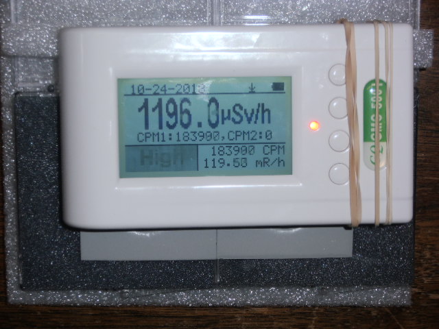
Here is a pic of the M4011 tube with both 5 and 10 uCi sources stacked with slight offset at center of tube. ~184,000CPM and ~1,200uSv/h
Image Insert:
79407 bytes
Here is the SI3BG in the same configuration. ~1,600CPM and ~1,280uSv/h
Image Insert:
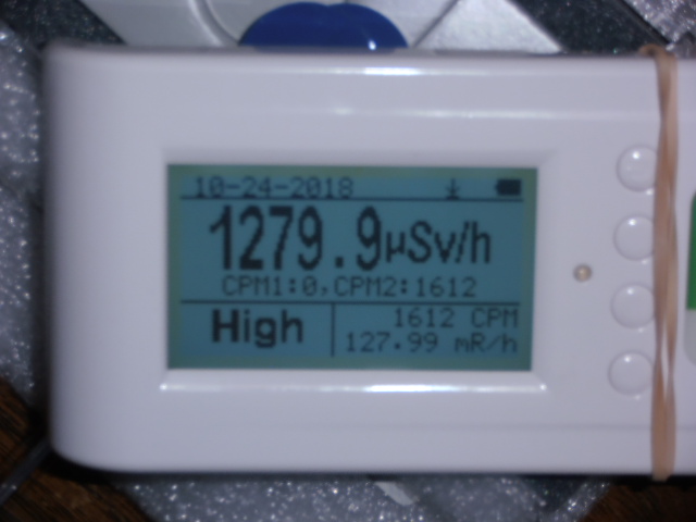
81027 bytes
In rough numbers, the 184,000 CPM has a corrected for dead time CPM of ~217,000CPM. In order for the SI3BG tube (with a dead time correction at 1,600CPM of only +9CPM) to match the corrected CPM of the M4011 tube at conversion to uSv/h (.0065) the SI3BG tube's conversion needed to be at 1.13CPM/uSv/h (.885). I had initially wanted to use .797 as the average of high and low given in specs, but in fitting the data I found lower end was better. The other significant change was I needed to lower the dead time of the M4011 tube to 50usec. ullix showed that dead time is somewhat insensitive adjustment, except at very high counts, and we really don't know yet what the actual dt of the M4011 is, so all is good in my opinion until we are comparing the two with working firmware to adjust the calibration with both conversion factor and tube dead time. That the dead time correction for the SI3BG is inconsequential at 1600CPM makes this pretty straight forward.
What my expectation is after this comparison, is that the dead time is going to be just one of the factors involved in getting the best calibration of the meter (both tubes to agree). It remains an important add, but we are going to find that once implemented the best numbers for conversion of both tubes and dead time for the M4011 tube will be essentially standardized, and for the out of the box performance of the meters we can say with some certainty that we are adequately incorporating the correction. The dead time of the SI3BG was estimated at 200usec for this test, but I don't think I'd worry much about that.
Further work here will wait till firmware is done. Then with three M4011 tubes and four SI3BG tubes in stock to get better averages I will go through this all again to see if I can come up with a better estimate of parameters for conversion and dead time in general. I also want to look at these numbers with shielded sources for gamma only. The mixed energy levels of betas and gammas are certainly affecting the numbers and the gamma response is what's in the specs.
@GQ, any update of timing on when this will be ready?
|
| ikerrg |
Posted - 10/27/2018 : 02:29:54
It is difficult to keep a record of the altitude, as the information on the LCD screens is only showed some time after take off and until some time before landing, as the screens are retracted for take off and landing. I did that last time the best way I could, but it is quite time consuming and this time I had to work during the flight. The flight was scheduled to depart at 17:30 (Geneva time, so 16:30 in counter time), but as there was a delay (I cannot say, but it was around 15 minutes), we might have taken off at 16:45 or 16:50, not sure. I did my last phone call at 16:35 from inside the aircraft before starting the taxi to the runway. Regarding the landing, I do not have any phone call or SMS to check the time, but it was before 18:20 for sure.
Here is the raw data of the flight: https://www.dropbox.com/s/7k6m6phujyr3ywn/Flight_GVA-LHR.rar?dl=0
|
| ullix |
Posted - 10/26/2018 : 23:41:50
Your data do look really nice. I am wondering about 2 features:
First, you seem to assume a non-linear increase of cosmic radiation with altitude, because you mention very little increase up to 3000m.
Second, the "alpine" profile at cruising altitude looks like being well beyond any Poissonian fluctuation. I suspect the flight went up and down to stay in some assigned flight corridors?
Would be great if next time you could register time of takeoff and landing, as well as altitude over time? |
| ikerrg |
Posted - 10/26/2018 : 09:02:16
We were delayed and the pilot said that he would try to recover the lost time by going a bit faster. And you have to consider that the radiation increases sharply above some altitude, so the flight might well be from 16:50 to 18:15 or more, and that is 1h 25 minutes. I actually saw just a little above ground background radiation when we were still at 3000 m.
Re the Poisson, I did it only of the flat top, about from 17:13 to 17:33. Even with that, I suppose the cosmic radiation cannot be considered constant. |
| ullix |
Posted - 10/26/2018 : 01:05:27
What kind of supersonic aircraft were you boarding in Geneva?
The graph shows a flight time from 1700h to 1800h, i.e. 1 hour straight from start to landing. The typical duration for that route of some 760km is 1h30min or even 2h? The clock in the 500+ is working correctly?
Re the Poisson Plot: It is applicable only for a constant radioactive source, which must not be moved relative to the counter for the duration of the measurement. When the source's intensity changes, like during a flight, it will become an overlapping set of an infinite number of Poisson distributions. A "good" or "bad" Poisson fit then has no meaning.
But, of course, it might still be a tool usable to verify that nothing unexpected has happened.
Try the FFT on the profile; you should at least see the 1h period being dominant.
|
| ikerrg |
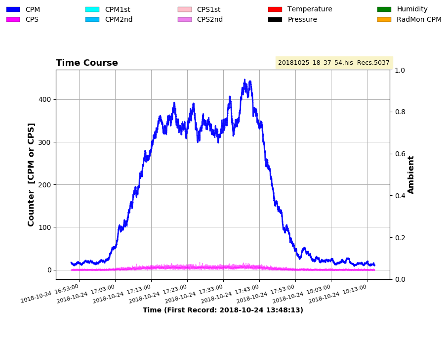
Posted - 10/25/2018 : 10:51:31
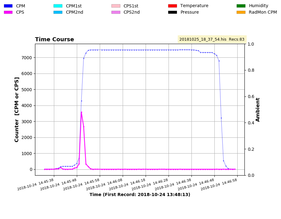
Here it goes an additional piece of data. My last flight from Geneva to Heathrow measured with the 500+V2 and now only using the sensitive tube (M4011). When passing through the x-rays, it peaked at 3581 CPS, with a total of 7025 counts in 5 seconds. This time, the M4011 tube did not look saturated, but the x-ray machine was different and the voltage in my 500+V2 was much higher than when I did the same in Heathrow last summer. I am starting to think that the Heathrow x-ray machines are much more powerful than in other airports! I need more trips and measurements to confirm this.
Image Insert:
61120 bytes
About the flight, it was quite a nice collection of data:
Image Insert:
84092 bytes
The Poisson distribution looks about right, considering that the cosmic radiation is not homogeneous at all.
By the way, @EmfDev, the parsed data from the DataViewer software is totally wrong again! I did the parsing with GeigerLog and it worked perfectly. Thanks ullix for such a great tool! |
| Stargazer 40 |
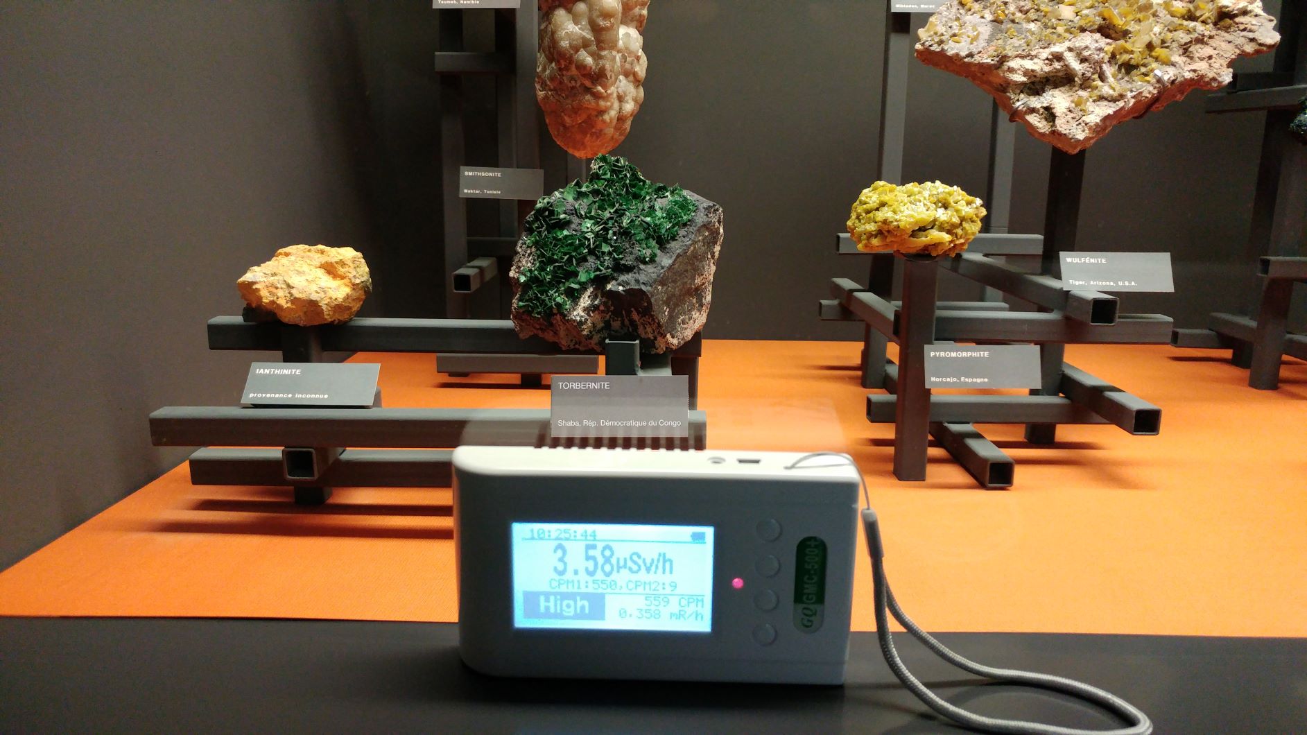
Posted - 10/22/2018 : 13:33:20
Very nice ikerrg. Thanks. A lot of work went into designing and building those display stands. Art in itself. I hope the museum techs are careful when opening this case. Torbernite outgases radon gas (222Rn). Case should be evacuated before opening. |
| ZLM |
Posted - 10/22/2018 : 12:44:47
Good picture. Thanks for sharing. |
| ikerrg |
Posted - 10/22/2018 : 11:21:15
And now just a bonus! This is a picture in the Natural History Museum of Geneva.
Image Insert:
458203 bytes
See the minerals behind the GMC. Torbenite and Ianthinite. They were driving the counter at very high count rates, considering the distance (about 150 mm) and the thick walled glass between the counter and the minerals. Nothing was said about the radiactivity in the area, it could be detected at quite long distance from the glass. And my guess is that it was mainly gamma, as I cannot imagine the betas going so far, and the SI-3BG tube was also very sensitive to it. I would have needed much longer times to get some statistics, but if you can find that amount of Torbenite you will probably be able to get a good source of gammas once the betas are filtered!
|
| Stargazer 40 |
Posted - 10/22/2018 : 10:35:02
Question for support@gqelectronicsllc.com I think. I don't know. |
| ikerrg |
Posted - 10/22/2018 : 10:02:02
That happens for both HV PS, the one for the M4011 and the one for the SI-3BG. Therefore, it would be related to both independent inductors. Do you expect that fitting the second inductor to the M4011 PS will change anything? |
| Stargazer 40 |
Posted - 10/22/2018 : 09:18:25
It's the inductor ikerrg. One V2 I have gets to 450VDC at 22%. The other gets to 450VDC at 27%. So as long as you can achieve top of the plateau range then PS is working okay. |
| ikerrg |
Posted - 10/05/2018 : 00:46:28
I measured the voltage directly with the 10MOhm multimeter @22% and it was 143V and 140 V. So either my multimeter does not have a precise 10 MOhm impedance (odd, because it is in the specs) or my 500+V2 has a voltage regulation much lower than Stargazer_40's. When I measured the old 500+ some time ago using the same voltimeter and 1 Gohm resistor I found very similar values to ullix's and everybody else, so my guess is that something is different in the HV PS of my 500+ V2. It might be the tolerance of the installed inductors/capacitors, no idea.
|
| ikerrg |
Posted - 10/04/2018 : 14:14:42
But that "calibration" is only for the CPM to uSv/h conversion, and that should be a constant, not a curve. And in any case, using only two points for the M4011 tube and 1 point for the SI-3BG does not allow for a nonlinear "calibration" dependent on the radiation level. So users can calibrate their device for, lets say, 1000 CPM, to be equal to 6.5 uSv/h but the same calibration would not work at 100kCPM, as 650 uSv/h would not be the equivalent dose rate because the tube is behaving nonlinearly at high CPM values, and the real equivalent radiation would be 150kCPM = 975 uSv/h. That is not a calibration by definition and, in any case, it would be impossible to be defined with only 1 or 2 points for the curve as it is currently programmed in the 500+ (V1 and V2).
The constant value that converts CPM to uSv/h depends only on:
- The tube construction (M4011, SBM-20, etc.)
- The type of radiation (beta, gamma, etc.)
- The energy of the radiation.
..and it is unmovable when the information above is known. Then the tube behaves nonlinearly, but that only affects the number of counts it reads which only depends on its recovery speed and the radiation intensity. The conversion to uSv/h would always be the "calibration" constant times the CPM!
|
| EmfDev |
Posted - 10/04/2018 : 12:58:10
We will think about it. As in the mean time, users can set the calibration settings
if they think that the measured dose rate is low in high radiation field. |
| ikerrg |
Posted - 10/04/2018 : 00:34:01
@EmfDev: Well, you do not need to correct the CPM if you do not really want to mess with that, although it could be an advanced option disabled by default in the menu. But you can at least use the rest of the algorithm to avoid adding the CPMs of both tubes when in combined (auto) mode. That sum is also a weird manipulation! In the spreadsheet you can see the effect of both options, they are completely independent to be implemented (the dead time correction and the combined CPM calculation, I mean).
About the average CPM, yes, that is exactly the calculation I would expect. It adds some minimal workload to the CPU every second, I suppose that would not be a problem. |
| EmfDev |
Posted - 10/03/2018 : 14:44:36
@ikerrg, we are still debating about that. Manipulating the cpm doesn't seem correct.
The average cpm will be changed in the next firmware update. Currently, the spike/fall happens in 30s or when there's a
tick in/out during the first few minutes. The new one will be calculated based on the 1/60 minute resolution. So
expect the reading to always change every second (average = totalcount/(minute + second/60). Is that correct? |
| ikerrg |
Posted - 10/03/2018 : 10:48:13
@EmfDev: I found an odd behaviour in the calculation of the average CPM. It seems that you are dividing the total count over the result of rounding half up to the nearest integer the elapsed minutes (e.g. 1� 35�� = 2). That produces big jumps in the average CPM value, especially when the number of minutes is small or after resetting the total count with the corresponding menu option. Could you use the decimal conversion of the elapsed time in minutes? (e.g. 1� 35�� = 1.583). Using that number, the average CPM value would be smoothly calculated every second without jumps every minute. |
| Stargazer 40 |
Posted - 10/03/2018 : 06:50:37
quote:
Originally posted by ikerrg
I think it can be done easier than changing the tube voltage in the voltage percentage menu. I noticed that the counts of the tube 1 (in the �Large text� screen) go to 0 when you select only the �Tube 2� in the menu. That didn�t happen in the original 500+, so I assume that the firmware is automatically turning off the voltage of the tube not being selected by the user.
I also confirm that if a tube is not turned on its voltage is a nominal couple of volts and not the percentage number in its tube voltage menu selection.
|
| ikerrg |
Posted - 10/03/2018 : 04:25:24
@EmfDev
So I have finally updated the Excel spreadsheet with the calculations that I would put into a Geiger counter firmware if it was mine (https://www.dropbox.com/s/95fs62jb2hc0n85/TubeCombination_v2.xlsx?dl=0 ). Please, take some time to analyse the inputs and outputs of the algorithm, which is based on the current statistical algorithm previously proposed by ullix. As for the inputs (the dark green cells), only the calibration and the dead times are required for each tube (4 numbers). The light green cells are only the external actual radiation inputs. Everything else is calculated from those 4 numbers (that are now just a guess) and the measured counts of the tubes.
You can see the limits of the tube 1 above 100 kCPM, and therefore I discourage the use of it above that radiation. From there on, tube 2 or the combination algorithm should be used (see the calculations in the spreadsheet). You can also see the measurement error between using corrected vs. uncorrected CPM values.
The three tables show how it would be the measurement using only tube 1, only tube 2 or the combination algorithm, both with and without the dead time correction. You should also add the possibility for the user to activate or deactivate the dead time correction; it is extremely easy for the algorithm. And remember that the combination algorithm is only useful if the radiation is homogeneous enough to be equally affecting both tubes (like in the current firmware). For inhomogeneous fields (small sources), tube 1 or tube 2 measurements are required (like in the current firmware).
This algorithm is the only possibility for the 500+V2 to get closer to the advertised 42500 uSv/h of maximum dose rate that are in the specs (http://www.gqelectronicsllc.com/support/GMC_Selection_Guide.htm ). It will be able to measure 8000 uSv/h with good accuracy or even 32500 uSv/h if the HV PS can handle the SI-3BG at that count rate. Obviously, those dose rates are enormous and we can only guess what the tube�s behaviour would be.
I cannot say anything else. Take your time to analyse the spreadsheet and it is your call to implement a good firmware algorithm to unleash the power of the 500+ V2, now that the hardware can keep the tubes in the flat top voltage region.
|
| EmfDev |
Posted - 10/02/2018 : 14:24:32
Also, when a tube is turned off or (0%) there should be ~3V between the terminals because of the power supply. |
| EmfDev |
Posted - 10/02/2018 : 14:09:58
We are going to look into changing the CPM.
As for the voltage, you can use a normal multimeter to measure it.
With a 10M-ohm multimeter, the reading should be around 150V. To check if your device has actually lower voltage.
The hole is there so that we don't worry anymore for any interferences. It might have worked same as without hole.
One of each RH1/RH2 and RH3/RH4 pair is 0 for flexibility. You can change it to anything when necessary.
|
| ikerrg |
Posted - 10/02/2018 : 13:09:43
Another comment that I forgot in the previous post. The new device has a hole on the PCB where the antenna of the WiFi module is located. I suppose that it is to avoid the RF shielding of the copper layer on the PCB. However, it would have had the same result if you had etched the copper on the surface beneath the antenna, as the PCB is just fiberglass and resin that it is totally transparent to the RF waves. I suppose that the PCB would have been a bit cheaper without that hole cut in the middle.
And does anybody know why there are now two anode resistors in series per tube? RH1 with RH2 for tube 2 and RH3 with RH4 for tube 1. This is a hi-res picture of the PCB: https://www.dropbox.com/s/3mr5fvqowz1kqf6/GMC-500%2BV2%20PCB2.jpg?dl=0
|
| ikerrg |
Posted - 10/02/2018 : 12:39:36
Looking forward to seeing the final voltages and pictures! So it seems that the additional inductor is actually needed to keep the voltage of the M4011 tube when measuring 100 kCPM? Could you tell the inductor characteristics?
The combination algorithm (if it works as expected) is only valid to combine the readings to get the dose rate in uSv/h. The CPM reading is still the addition of both tube CPMs, afaik. With your radioactive sources you could now check how the combination algorithm is working by taking the CPM and uSv/h readings at different radiation levels. This is the next stage of this debugging process. I think GQ should program the combination mode (tube 1 + tube2) in a way that the CPMs are not added, but just combined using the tube�s programmed sensitivity ratios. In http://www.gqelectronicsllc.com/forum/topic.asp?TOPIC_ID=5304 reply #22 and following ones, the algorithm seems to be applied to the calculation of the dose rate in uSv/h, but there is no reason to not to apply it to combine the CPM of both tubes:
CombinedCPM = (tube1CPM*tube1Weight + tube2CPM*tube2Weight*X)/(1+X)
where X = sqrt(tube2weight/tube1weight)
and then the dose rate in uSv/h is straightforward by multiplying the CombinedCPM*tube1sensitivity (the famous 0.0065).
@EmfDev: What are your thoughts about that?
I did an Excel spreadsheet some time ago to prove the algorithm, I can review it now that the hardware is capable of driving both tubes.
On the other hand, I am getting these voltages with the DMM connected.
@22%
M4011: 366 V
SI-3BG: 359 V
@26%
M4011: 404 V
SI-3BG: 397 V
So, much lower voltages that your device, Stargazer_40. There is the uncertainty of the 1GOhm tolerance and the DMM internal impedance, but it seems too much of a difference!
And by the way, I can confirm that the voltage of the non-selected tube is close to 0, so it seems that the 500+V2 is turning off the tube that is not measuring! Well done, GQ!
|
| EmfDev |
Posted - 10/02/2018 : 12:39:23
@ikerrg we will try to see where we can put that icon because the top right of the screen is kind of full. |
| Stargazer 40 |
Posted - 10/02/2018 : 05:54:43
I have added the inductor to the tube 1 augmenting power supply, turning it on. With comments made about a 10 volt increase for 1GOhm meter effect, I believe my measurements so far show that the 500+ with the second tube1 power supply added in and voltage set at the upper end of the plateau (440VDC) supports the 5uCi source (properly placed) in the plateau region of M4011 voltage. This makes the DIY component adds a good thing if you want to make use of the M4011 tube independently of the SI3BG tube. That said, if you're wanting to use the pair of tubes in tandom (as originally designed), then the power supply as we have said through all ullix's work and some of what I've presented shows that 30,000CPM (crossover point for tube1 to tube2) can be supported by the independent power supplies of the V2 as shipped. We still have to work with conversion factors though and ikerrg's access to some high gamma counts is very much welcome. I will show the data from the meters when I resolve a better voltage out terminal structure. The V2 meters don't have that handy capacitor PCB hole that I was able to solder a wire to on the tube1 power supply of the original 500+ that I have, so I have to clip to the tube clips and that is fraught with mechanical instability at this point. |
| ikerrg |
Posted - 10/02/2018 : 01:20:09
I finally received my new device and I will start testing it as soon as I find some spare time. Stargazer_40 has already gone through a good battery of tests, so I do not want to repeat those, and in any case, I do not have the radioactive sources to drive the tubes to such high CPM counts. So, for the time being, I will try to find other problems (firmware bugs, inconsistencies, improvements, etc.). I already noticed a few minor tolerance issues in the manufacturing of the unit that I reported to the technical support.
I am still waiting for the opportunity to go to a high radiation area in my work place. That would be mainly gamma radiation and in a big volume (i.e. about homogenous), so very useful to finally find the ratio of sensitivities between the two tubes. And as Stargazer_40 confirmed, the new version is not limited by the parallel connection of two very different sensitivity tubes, and therefore I see this new GMC-500+ as a really capable and promising device!
quote:
Nice to be able to turn off the M4011 in the V2!
I think it can be done easier than changing the tube voltage in the voltage percentage menu. I noticed that the counts of the tube 1 (in the �Large text� screen) go to 0 when you select only the �Tube 2� in the menu. That didn�t happen in the original 500+, so I assume that the firmware is automatically turning off the voltage of the tube not being selected by the user. I will confirm that this night when I can find time to do some voltage measurements. That is something that I requested some time ago to save the tube�s lifetime, especially when you activate only tube 2 and you want to do high radiation measurements (saving M4011 life). I am happily surprised on how GQ has been listening to us these months and has implemented so many fixes to this new release of the 500+.
@EmfDev: Please, check my previous reply#11 in this thread for a firmware improvement. I think that a small icon at the top right corner would be very helpful to quickly identify in which mode the device is working (Tube1/HS, Tube 2/LS or Auto).
|
| ullix |
Posted - 09/28/2018 : 02:10:59
There is a whole bunch of pulse width measurements done by myself and others here:
http://www.gqelectronicsllc.com/forum/topic.asp?TOPIC_ID=4598
Read carefully and note the impact of capacitance!
Not mentioned there is the impact on the Poisson distribution; make sure you look at that carefully. Very important!
|
| Stargazer 40 |
Posted - 09/27/2018 : 07:09:20
I agree, as I had the original meter a couple inches away on tube 1 and it was adding between 100 and 200CPM from the proximity to the source. Nice to be able to turn off the M4011 in the V2! |
| ikerrg |
Posted - 09/27/2018 : 06:21:19
I think you should always use the "Large text" screen with the corresponding option activated to see the CPM of both tubes at once. If you take a picture to that screen, then you will be able to see later if the other tube was measuring counts and what number, to see if the results could be cross-talking. This is not so important for the 500+ V2, I suppose, as the cross-talk is small or non-existing.
|