| Author |
 Topic Topic  |
|
EmfDev

2418 Posts |
 Posted - 07/13/2018 : 15:19:15 Posted - 07/13/2018 : 15:19:15


|
We did some modifications to the code. But it's not official yet.
GETCPM, GETCPMH, GETCPML, GETMAXCPS, GETACPM, GETCPS, now return
4 bytes of data. Turning HEARTBEAT1 will also report 4 bytes of data
per second.
Also added GETCPSH, GETCPSL, and looping through menu.
We tried to implement @ullix's uSv formula from https://www.gqelectronicsllc.com/forum/topic.asp?TOPIC_ID=5278
where weights can also be adjusted,
uSv = (tube1Count * tube1Weight + tube2Count * tube2Weight) / 2 * <calib.usv/calib/cpm>
In this formula, if tube2Weight is high for the example 30, then 1
count(cant be noise) in tube 2 will significantly change the resulting uSv in lower levels of radiation.
One way to fix this is to ignore tube2Count until certain level and only use tube1Count (best is until tube1 saturation count) but
we need time to determine those values. It's hard to find the saturation count because each tubes have different saturation limit. |
|
| Reply #1
ikerrg

United Kingdom
334 Posts |
Posted - 07/13/2018 : 23:40:42
|
Good! All that looks a step in the right direction to make sense of the dual tubed GMC-500+ and make it behave as specified. Thanks for hearing the users!
I suppose you will also have to change the way the GMC-500+ saves data to the internal memory. If it is now reporting 32 bits for the counters, it should be possible to store that data in the internal log. And if you could add a "debug" mode so the GMC-500+ can store independently (in the internal memory) the counters for both tubes, that would make much easier any future debugging of the merging algorithm.
|
Edited by - ikerrg on 07/14/2018 00:44:40 |
 |
|
| Reply #2
ullix
Germany
1247 Posts |
Posted - 07/14/2018 : 04:57:40
|
I join ikerrg in the complements!
With an eye on programming, I don't feel quite the excitement . At least, please, please, please, also add a function call, which allows to determine the byte-size the answers will have! And which gives an answer even in the old counters! . At least, please, please, please, also add a function call, which allows to determine the byte-size the answers will have! And which gives an answer even in the old counters!
quote:
uSv = (tube1Count * tube1Weight + tube2Count * tube2Weight) / 2 * <calib.usv/calib/cpm>
In this formula, if tube2Weight is high for the example 30, then 1 count(cant be noise) in tube 2 will significantly change the resulting uSv in lower levels of radiation.
Actually, it is easier. We should just remember the statistical properties of a Poisson distribution. (see my article ... oh, I think you know)
For Poisson the average equals the variance, or in other words: the Standard Deviation (StdDev) equals square root of average. The relative StDev is an indication for the uncertainty. In the above formula we implicitly used a weighting factor of 1. This now becomes the StdDev instead. Let's see:
Our first tube may have a tube1weight of exactly 1, and our 2nd tube of exactly 30. At a count rate for the 1st tube of 10000CPM, the StdDev is sqr(10000)=100, and relative StdDev = 100/10000 = 1%. (I will now use fractional counts to avoid any extra confusion due to rounding errors). With two count rates of 10000 and 60000
1st: CPM=10000,   StdDev=100,     relative StdDev=1%
2nd: CPM=333.333, StdDev=18.257,  relative StdDev=5.48%,  relative to 1st tube: 5.48x

1st: CPM=60000,   StdDev=244.949, relative StdDev=0.408%
2nd: CPM=2000,    StdDev=44.721,  relative StdDev=2.236%, relative to 1st tube: 5.48x
The uncertainty (= StdDev) becomes relatively smaller with increasing count rates, but the ratio between those errors remains the same at 5.48 fold.
Well, not surprising when we write down the complete formula, the 5.4 is simply the value sqrt(30)!
You can therefore account for the lower errors of the 1st tube by giving it an extra weight of sqrt(30)=5.48fold, and the 2nd tube only of 1.
(10000 * 1 * 5.48 + 333.333 * 30 * 1) / (5.48 + 1) = 9999.998
and for CPM=60000 at the 1st tube:
(60000 * 1 * 5.48 + 2000 * 30 * 1 / (5.48 + 1) = 60000.000
Your microprocessor must learn square roots, but otherwise it is very straight forward.
The question remains whether you should do any averaging at all, and not just switch at a predetermined count rate value?
|
|
|
| Reply #3
ikerrg
United Kingdom
334 Posts |
Posted - 07/14/2018 : 10:21:20
|
quote:
The question remains whether you should do any averaging at all, and not just switch at a predetermined count rate value?
I kind of agree with that, ullix. I think we might be complicating things here. The purpose of the second tube is just to help counting radiation when the first tube gets nonlinear or cannot keep with the high number of events per second. And we do not have to forget that the final purpose is to measure the equivalent dose rate in uSv/h, which is the amount of energy (Joules) released by the radiation per kilogram of live tissue and hour of time (assuming always beta or EM radiation to avoid complicated conversion factors). The CPM or CPS is just a dose rate which, for the same external radiation, depends only on the tube type, and it is useful as a relative measure for the same tube and different radiation levels, but not as an absolute number. Therefore, trying to combine both tubes CPMs in one number does not make much sense, as we can already get a comparative dose rate in CPM by comparing the CPML or CPMH at different radiation levels. Hence, for comparative CPS or CPM measurement, the GMC-500+ should show and store those values for each tube, as those are the real events detected in the tubes. No attempt to combine them makes too much sense from my point of view.
About the real dose rate, we should aim to convert the measurement of both tubes in one meaningful dose rate (SI units, i.e. uSv/h), and the best way to do that is just by using the CPMH measurement and calibration of the second tube (0.194) when the first one reaches a defined CPS value (and not CPM as that would be too slow to respond). We can consider the second tube linear up to the detection limits of the device. Given that the second tube should already be quite sensitive when the external radiation is more than 325 uSv/h (more than 1675 CPM or 28 CPS), and that the first tube should still be linear (as that is the maximum measurement range of the GMC-320+ featuring only one high sensitivity tube), I think we could switch above that number, i.e. we use the CPML reading and the calibration 0.0065 when the CPSL is less than 50000/60 and use the CPMH with the calibration 0.194 when the CPSL is more than 50000/60. If there is a possibility in extremely high fields to saturate the first tube so it could stop counting at all (or reading less than 50000/60 CPS), the algorithm could use instead the CPSH as a comparison value (i.e. only use the first tube when CPSH is less than 1675/60 and the second tube when the CPSH is more than 1675/60).
By the way, I am assuming a radiation field big enough to be homogeneous in the distance between both tubes (which is usually true). However, if for example a small bit of radium is put near only one of the tubes, these calculations would make no sense at all, and the switching algorithm would not work as expected. In that case, also the idea of dose rate in uSv/h makes no sense, as that assumes a homogenous distribution of the radiation in the measurement volume. As a workaround, the firmware could check if the CPSH reading of the second tube is much less than expected according to the ratio of linear sensitivities (0.194/0.0065) and then pick only one of the tubes (the one with the highest normalized reading) for the CPM output and the conversion to uSv/h. I have to admit that the algorithm becomes a bit complex if you want to take into account all the possibilities in non-homogeneous radiation fields.
In summary:
-Show and store CPMs and CPSs for both tubes.
-To calculate the uSv/h:
*Use the M4011 tube�s CPM for measurements in the M4011 lower than 50000/60=833.34 CPS (uSv/h=CPM*0.0065) and the SI-3BG�s CPM above that (uSv/h=CPM*0.194).
Or alternatively:
*Use the M4011 tube�s CPM for measurements in the SI-3BG lower than 1675/60=27.92 CPS (uSv/h=CPM*0.0065) and the SI-3BG�s CPM above that (uSv/h=CPM*0.194).
After implementing any of this changes in the firmware, it should be easy for you to test their final validity with two signal generators and different radiation scenarios. We could write a QA testing procedure for the inputs (signal generators frequencies) and the expected outputs.
Thanks again for reading this, and I hope all this makes sense to you.
|
Edited by - ikerrg on 07/14/2018 15:20:14 |
|
|
| Reply #4
EmfDev
2418 Posts |
Posted - 07/16/2018 : 10:58:17
|
We reviewed the formulas none of them are significantly better than the current algorithm in all cases.
The main problem is figuring out when to switch. In the above formula, it is very inaccurate at background radiation.
And switching can produce a huge jump in the reading which can confuse most of the users.
|
Edited by - EmfDev on 07/16/2018 10:59:20 |
|
|
| Reply #5
ikerrg
United Kingdom
334 Posts |
Posted - 07/16/2018 : 11:24:03
|
Then the two tubed device is useless. If you cannot combine the reading (inaccuracy at low readings) and you cannot switch between them at high radiation levels, it is clear that there is no point in having two tubes. Adding both CPM count rates is not accurate also, and makes no sense for different sensitivity tubes, because you cannot apply only one conversion rate for the sum of both tubes CPMs. At least, if you could show and store the count data for both tubes independently, we would be able to do our own algorithms. And for the uSv/h, you can calculate them independently per tube with the corresponding calibration factor (for high readings) and then average both numbers.
I think that the users that could benefit from the reading of the low sensitivity tube are the ones that know what they are doing, and they won�t be confused by the jump. Most of the users would never see the jump, because you require 325 uSv/h!!
|
|
|
| Reply #6
ullix
Germany
1247 Posts |
Posted - 07/17/2018 : 01:39:21
|
quote:
We reviewed the formulas none of them are significantly better than the current algorithm in all cases.
The main problem is figuring out when to switch. In the above formula, it is very inaccurate at background radiation.
And switching can produce a huge jump in the reading which can confuse most of the users.
Oh, please. Your 'current algorithm' is wrong, pointless, nonsense, not worth talking about.
What "above formula"? I did give you a way to properly accommodate both tubes according to their statistical relevance. That is a world apart from a sum of the two unweighted CPMs!
And why is the switching point a problem? You can determine the response curve of the high sensitivity tube and pick a point sufficiently high and sufficiently before saturation. Just for an argument, say this is 25000. The 2nd tube would then have a statistical error of 3% at an environment of 160�Sv/h. Didn't you say something about 15% is acceptable at GQ? This would be 5 times better.
And there won't be a jump within statistical uncertainties. None, nada, nothing, nix. Provided, however, your calibration factors are correct. Though currently these seem to be grossly incorrect, as judged by our data. You must have tested that during develpment. Can you provide better data?
Well, you are marketing these devices with certain specs. Yet, you don't seem to be able to provide any evidence that you have ever tested these devices, not even with a signal generator, let alone in a real world setting. It seems that only one user has tested this, and it failed miserably.
I think it is time to discuss "recall" before someone looks at "fraud"!
|
|
|
| Reply #7
ikerrg
United Kingdom
334 Posts |
Posted - 07/17/2018 : 02:36:22
|
I do not want to be so radical in my opinions, but I have to agree with ullix. You have to think about the best option and use it. The worst action is no action this time! And everything is there, I mean, the hardware is capable enough to count events from both tubes, so it is only a firmware algorithm problem (no recall needed). It just requires you guys to sit down and brainstorm until you find the best solution. You can use ullix's ideas or my ideas as a base, but do something, please! At least I'd like to be able to disconnect (by software) the second tube so it does not interfere by adding uncertainty to my readings. That can be easily done just by logging the readings of both tubes independently to the internal memory.
Again, we do not need to combine the CPMs of both tubes at all, we only need to see both counts separately. And we need to think how to show the equivalent dose rate in uSv/h, with plenty of possibilities as I explained in previous posts, i.e. switch between tubes or average the uSv/h after the individual calculation of uSv/h for each tube, neglecting the second tube for very low radiation levels.
Please, do something. The device is great and it has great possibilities. It only needs a few hours of thinking and a day of reprogramming.
|
Edited by - ikerrg on 07/17/2018 02:42:47 |
|
|
| Reply #8
EmfDev
2418 Posts |
Posted - 07/17/2018 : 09:58:15
|
Thank you for all input. We never said we'll do nothing. We are thinking better ways to use your algorithms.
Might need some time. |
Edited by - EmfDev on 07/17/2018 10:00:21 |
|
|
| Reply #9
ikerrg
United Kingdom
334 Posts |
Posted - 07/17/2018 : 10:19:04
|
| Thanks EmfDev. I look forward to seeing your final solution to the problem! Please, keep us informed whenever a firmware update is released. |
|
|
| Reply #10
EmfDev
2418 Posts |
Posted - 07/17/2018 : 10:25:57
|
** This is for calculating uSv/h, the CPM displayed will still be the sum of both tubes.
for calculating uSv/h
We thought of using tube1 for cpm lower than 30k. Then use the formula
(10000 * 1 * 5.48 + 333.333 * 30 * 1) / (5.48 + 1) = 9999.998
if tube1 is higher than 30k. However, we need to find a point where
we need to use tube2 instead of tube1 at <30k tube1cpm if tube2 uSv/h convertion (tube2count*.195)
is significantly higher than tube1 uSv/h convertion. It can happen if the users try to put a source
much close to the low sensitivity tube. So need to find point where the uSv/h convertion of tube2
is significantly high enough that we only use the tube2(or both). can also happen during saturation.
Then tube 2 can go much higher than tube 1. |
|
|
| Reply #11
ullix
Germany
1247 Posts |
Posted - 07/17/2018 : 23:46:48
|
@EmfDev: I am not sure I can follow.
Are you now trying to accommodate a user who inappropriately handles the counter by bringing it into an inhomogeneous radiation field, where one tube gets more than the other?
Don't!
It is your responsibility to explain to the user the more demanding requirements of this more complex counter (here a homogeneous radiation field). But for your firmware you assume this condition is met. It is complicated enough anyway.
Your true main problem is the saturation of the 1st tube. At a certain point, at the very latest at CPS=5000, the tube will be in saturation and probably not deliver any counts at all, because they follow so close to each other that the electronics cannot distinguish between them. And even if it could, we'd see CPM=300 000, which it coulnd't handle as a 16bit number, limited to 65000.
To avoid this, well before this limit, the tube must be switched off. Preferably by switching off the high voltage, but at least by switching off the access to the counting circuitry.
Let me ask: Is it even possible to switch off the 1st tube in this way in the current 500+ unit?
|
|
|
| Reply #12
ikerrg
United Kingdom
334 Posts |
Posted - 07/18/2018 : 01:20:30
|
Adding both tube�s CPM is like adding pears and apples. They are not the same at all, the sum does not represent anything.
Anyway, about the uSv/h conversion:
- First of all, the conversion in the present calibration is not 0.195, but 0.194 (4.85/25). I suppose that those numbers for the formula will be taken from the user customizable calibration in the device, so their exact value does not matter at this time.
- Assuming that the tube 2 is working as expected, at 195 uSv/h (30000 CPM in tube 1) it should be quite sensitive by itself (detecting about 1005 CPM or 16.75 CPS), so I do not see why we need to consider the tube 1 above that radiation level. The formula you proposed cannot take into account an unknown reduction in sensitivity of the first tube with increasing CPM, and it will keep returning the CPM readings of the tube 1 slightly corrected by the readings of tube 2 (but still with plenty of error), hence the conversion to uSv/h will be wrong at higher radiation levels (see and play with the spreadsheet in https://www.dropbox.com/s/bj3tgun2z3b9xpf/TubeCombination.xlsx?dl=0 ).
- I agree that for non homogeneus radiations (when the CPMs are not related by the sensitivity ratio of the tubes), the firmware should return the readings of only the biggest corrected reading from both tubes, or just do nothing due to a wrong use of the device as ullix says. It is easy enough though that if the first tube is reading 1000 CPM and the second is reading 6.7 CPM, the firmware could internally calculate the dose rate of both independently (6.5 uSv/h and 1.3 uSv/h respectively in this case) and discard the lowest one.
- There is another option, which probably is the best one. Add a menu option so the user can select which tube to get readings from, with the options �high sensitivity tube�, �low sensitivity�, and �combination�. In this way, the user that only does background radiation, will have their devices set at "high sensitivity" and only the data from tube one and the conversion factor for tube 1 would be used. The user that wants to play inside the Fukushima reactor can select �low sensitivity�, or �combination� where the previous algorithm will be used by the software to automatically combine or switch between tubes.
I hope I did not say something too stupid ;)
|
Edited by - ikerrg on 07/18/2018 01:23:56 |
|
|
| Reply #13
EmfDev
2418 Posts |
Posted - 07/19/2018 : 11:19:41
|
The display CPM is just there to display, but the uSv/h is calculated differently.
I remember I mentioned before from other threads that the counter is 32 bits and can handle up to 65KHz (3.9M CPM for each
tube).
Not all tubes(tube2) have same sensitivity at lower level of radiation that's why the calibration of tube 2 is 30 times
of tube 1 because is was assumed to be a low sensitive tube and is tested in high levels of radation. |
|
|
| Reply #14
ullix
Germany
1247 Posts |
Posted - 07/20/2018 : 00:01:09
|
@EmfDev: quote:
Not all tubes(tube2) have same sensitivity at lower level of radiation that's why the calibration of tube 2 is 30 times of tube 1 because is was assumed to be a low sensitive tube and is tested in high levels of radation.
So you have tested the tube in high levels of radiation? Can you show us the data?
I am very surprised about your claim that the tube has lower sensitivity at low radiation level. I never heard that before, and I find it hard to imagine given the mechanism of its functioning.
When a count is generated in the tube, the pulse of the electric discharge in the tube plus any pulse lengthening in the electronics last 0.2 millisecond (or less). At high rates the tube then sits idle for, let's say, a millisecond before the next pulse comes, or only 5 times the pulse length, it responds well. But when the tube has to wait for 1000 milliseconds, totally undisturbed, everything well charged, the tube becomes less responsive?
I think this is a major discovery, which will certainly have been published somewhere. Please, provide us with a link or reference to your source for this important information.
I had asked a question ina previous post, which you may have overlooked; I'd appreciate an answer:
quote:
Let me ask: Is it even possible to switch off the 1st tube in this way in the current 500+ unit?
|
|
|
| Reply #15
EmfDev
2418 Posts |
Posted - 07/20/2018 : 10:28:07
|
Someone else tested and I don't have access to the data.
I think you misunderstood my statement, I was saying different tubes will have different sensitivity.
There are 2 independent 32bit counters attached to each tube. We can switch off the counters or just ignore
its reading. But what is the point? |
|
|
| Reply #16
Stargazer 40
USA
431 Posts |
Posted - 07/20/2018 : 12:04:18
|
Thanks for going through all this. I do like the idea of the last sentence in first post -
"One way to fix this is to ignore tube2Count until certain level and only use tube1Count (best is until tube1 saturation count) but
we need time to determine those values. It's hard to find the saturation count because each tubes have different saturation limit."
and of using only a single tube at a time. I agree that there is likely a cutoff number that will work quite well with an estimate of saturation of the more sensitive tube and not have poor performance of the less sensitive tube. Hopefully GQ can go through some testing and come up with a number that works the majority of times. Just ordered a 500+ and given this conversation have some concerns about just what the two tubes are telling me if they are combined somehow.
Thanks |
Stargazer 40 |
|
|
| Reply #17
EmfDev
2418 Posts |
Posted - 07/20/2018 : 14:32:07
|
@Stargazer
Thanks for your comments. Yeah we just want to improve the GMC-500+ uSv conversion.
@ullix, @ikerrg
As of now, we have
if tube1CPM < 30,000, then uSv/h = tube1CPM*(calib_usv/calib_cpm) ==>> this will give equal uSv/h as GMC-500, 300, and 320
OR
if tube1CPM < 30,000, then uSv/h = (tube1CPM*tube1Weight + tube2CPM*tube2Weight)/(1+1) * (calib_usv/calib_cpm)
But we might want to
if tube1CPM > 30,000, then uSv/h = tube2CPM*(calib_usv/(calib_cpm*(tube2Weight/tube1Weight))) (only tube2)
OR
if tube1CPM > 30,000, then uSv/h = (tube1CPM*tube1Weight + tube2CPM*tube2Weight)/(1+1) * (calib_usv/calib_cpm)
this willl give the average of the 2 tubes but we might want to increase the weight of tube2 so that
it can reduce the error during tube1 saturation.
==> uSv/h = (tube1CPM*tube1Weight + tube2CPM*tube2Weight*X)/(1+X) * (calib_usv/calib_cpm) where X = sqrt(tube2weight/tube1weight)
There is also
if( (uSv/h of tube2 - uSv/h of tube1)/uSv of tube1 is greater than 10%?, then we will use uSv/h of tube2,
also vice versa if tube1 uSv/h is significantly greater than tube2
This is to reduce errors in non-homogeneous radiation fields.
The tube weights can be configured by the user.
@ikerrg, Sorry but I don't think we will support saving both CPSs to the EEPROM, at least not in GMC_500+. |
Edited by - EmfDev on 07/20/2018 15:03:56 |
|
|
| Reply #18
Stargazer 40
USA
431 Posts |
Posted - 07/20/2018 : 14:59:22
|
And to be clear the tube 1 solution is limited to 4250 uSv and the tube 1 and 2 solution is limited to 42500 uSv?
If I could implement all three of the solutions EmfDev just laid out in settings, I think that would be great. I wouldn't know how they could be tested however on the higher limits, so likely would simply employ the one that above 30,000CPM only makes use of tube 2. For me it's about order of magnitude of radiation, not lab critical number.
Also if 30,000 counts exceeded and switch to tube 2 or one of the combined mixes, it would be nice if the 'HIGH' warning could change to something like 'LETHAL'
Thanks |
Stargazer 40 |
|
|
| Reply #19
EmfDev
2418 Posts |
Posted - 07/20/2018 : 16:03:43
|
From the previous algorithm, the limit is 4250 uSv/h for 500, and 42500 for 500+. I am not sure how it was calculated (probably testing
the limit to high radiation). I'll have to check later. 4250 uSv = 655350 CPM
But in the new solution, the the limit will be the max CPM (saturation) of both tubes.
As long as the processor can handle the counts (up to 3.9 Million CPM or 65000 CPS for each counter),
but the Tubes will already be saturated far before they reach that CPM.
The problem of just switching to tube2 (only) above the threshold 30000 CPM is,
if tube1 is 30,000CPM (195 uSv), we expect tube2 to be 1000 CPM (195uSv), but the reading
won't be exactly 1000CPM, it can vary maybe 900, 800, 1200 CPM, or even higher or lower,
then the uSv reading will be at the maximum error compared to if we average them. It can also
confuse the user for example if you are moving closer to a high radiation source and the tube1 count jumped from 29000
to 3100 but tube2 during that time is 900, then you will notice the uSv convertion is now much lower
than your expected value because it used the 900 to convert it to uSv (we expect more than 1000CPM to get the expected uSv).
But we'll see which one we'll be using.
Right now the firmware should be good for your liking if you're not concerned about critical numbers because the
algorithm is coded that way.
Hahaha most cases people will already know they're in lethal range if they see that much CPM.
|
Edited by - EmfDev on 07/20/2018 16:09:33 |
|
|
| Reply #20
Stargazer 40
USA
431 Posts |
Posted - 07/20/2018 : 18:37:51
|
We really then need to deal only with the transition from all tube 1 to all tube 2, smoothing that out. The line above about switching to all tube 2 when (uSv/h of tube2 - uSv/h tube1)/uSv of tube1 is greater than 10% may make actual smoothing algorithm less critical if getting to that point is narrow range of CPM increase versus jump to tube 2 uSv/h.
To be honest, I think safest approach may be to simply manually set range of meter by menu to either tube1 or tube2 with indicator on display. Like analog meters of old with simple switch for 5, 50, 500 mR/H. |
Stargazer 40 |
|
|
| Reply #21
ikerrg
United Kingdom
334 Posts |
Posted - 07/21/2018 : 04:28:49
|
@EmfDev,
First of all, congratulations for the support that you are providing about this problem. We are much closer now to unlock the real potential of the GMC-500+!
Whatever is the algorithm that you finally pick to automatically calculate the uSv/h with both tubes at low and high ranges (like the autorange in a multimeter), I still think that the best option to add to the device is what I proposed some days ago in Reply #12:
quote:
- There is another option, which probably is the best one. Add a menu option so the user can select which tube to get readings from, with the options �high sensitivity tube�, �low sensitivity�, and �combination�. In this way, the user that only does background radiation, will have their devices set at "high sensitivity" and only the data from tube one and the conversion factor for tube 1 would be used. The user that wants to play inside the Fukushima reactor can select �low sensitivity�, or �combination� where the previous algorithm will be used by the software to automatically combine or switch between tubes.
By this way the user can select �manual range� and pick one of the two options ("high sensitivity" or "low sensitivity"), or select �auto range�, and the firmware does the combination with any of the proposed methods (it might also indicate on the screen which range it is using as Stargazer 40 was proposing). With this menu option, the advanced user could also find the sensitivity of both tubes independently when immersed in the same radiation field, and therefore set customized calibration factors with much more accuracy. It is a win-win option!
Now, only about the automatic �auto range� algorithm:
quote:
The problem of just switching to tube2 (only) above the threshold 30000 CPM is, if tube1 is 30,000CPM (195 uSv), we expect tube2 to be 1000 CPM (195uSv), but the reading won't be exactly 1000CPM, it can vary maybe 900, 800, 1200 CPM, or even higher or lower, then the uSv reading will be at the maximum error compared to if we average them.
That is effectively saying that the sensitivity of tube 2 is not known and the calibration factors we use are not good. OK, to smooth that behavior whatever the calibration factor is, you could easily add a comparison that makes sure that the switching from tube 1 to tube 2 only happens when the CPM in tube 2 is enough to match the uSv/h calculation from tube 1. And the same in the opposite direction. Something like:
quote:
if( (uSv/h of tube2 - uSv/h of tube1)/uSv of tube1 is greater than 10%?, then we will use uSv/h of tube2, also vice versa if tube1 uSv/h is significantly greater than tube2.
After doing some simulations in Excel (download it here: https://www.dropbox.com/s/n4xjnfddmfpeahg/TubeCombination2.xlsx?dl=0 ), my vote goes for these options (three ranges):
1.- if tube1CPM < 30,000 (CPS < 500) then uSv/h = tube1CPM*(calib_usv1/calib_cpm1) ==>> this will give equal uSv/h as GMC-500, 300, and 320. The other option that you propose is very good if saturation of tube1 starts earlier that 30,000, but it adds complexity and weighting factors to something that is not actually needed.
2.- if 30,000 < tube1CPM < 60,000 (or any other higher value) then uSv/h = (tube1CPM*tube1Weight + tube2CPM*tube2Weight*X)/(1+X) * (calib_usv1/calib_cpm1) where X = sqrt(tube2weight/tube1weight), as you proposed.
3.- if tube1CPM > 60,000 (or any other higher value) OR tube2CPM > 2000 (or any other higher value) then first check if (tube2CPM*(calib_usv2/calib_cpm2)) > (tube1CPM*(calib_usv1/calib_cpm1)) and, if true, then uSv/h = tube2CPM*(calib_usv2/calib_cpm2) (only tube2 data being used). If false, keep using tube1 until the condition is met. This third range avoids the big error that will happen if tube1 sensitivity drops massively in high radiation for whatever reason (try in the attached Excel), and it seems sensible to use only tube2 at very high radiation levels. I still think that you should show on the screen both CPMs of the tubes independently (there is space on the screen!), but if you prefer a combined number at this 3rd step that is continuously smooth with the step 2, you can continue showing the combined CPM as calculated in step 2, i.e. CPMequiv = (tube1CPM*tube1Weight + tube2CPM*tube2Weight*X)/(1+X). Again, see the effect in the Excel file.
In your formulas, when you say (calib_usv/calib_cpm), I suppose you are always referring to tube1 values (0.0065). I have specified above whether the numbers are from tube1 (0.0065) or tube2 (0.194). For the tube weights, I suppose that they are automatically calculated from the calibrated sensitivities, with no need for additional user input for the weights.
And I would use CPS for the comparisons because at these high radiations the jump between steps depends a lot on the distance to the source, and the user might want to see the instantaneous dose rate in uSv/h without having to wait around 1 minute for the auto range algorithm to swap between calculations.
|
Edited by - ikerrg on 07/21/2018 05:31:51 |
|
|
| Reply #22
EmfDev
2418 Posts |
Posted - 07/23/2018 : 10:10:09
|
Thanks for all your inputs, we will try to implement this:
3 options for the user to select,
1. Tube 1 (Low dose tube) only use tube 1
2. Tube 2 (High dose tube) preferable for high CPM/S readin
3. Combination.
in 3, there's only 2 steps calculation.
1. if CPM < SOME_TRHESHOLD, then use tube1CPM
2. else use uSv/h = (tube1CPM*tube1Weight + tube2CPM*tube2Weight*X)/(1+X) * (calib_usv1/calib_cpm1) where X = sqrt(tube2weight/tube1weight)
**The threshold depends on the second calibration CPM data of tube 1
** this is just to avoid complexity in picking which tube to use,
since the user can already pick which tube to display.
From the menu, after changing which tube to use, user might want to
restart the device to reset the counts.
For 500+ users, there will be an option to display tube1, and tube2
CPM's in the large font mode.
The CPM displayed and SAVED to the memory will be the CPM/S of the
selected tube. |
Edited by - EmfDev on 07/23/2018 13:52:26 |
|
|
| Reply #23
ikerrg
United Kingdom
334 Posts |
Posted - 07/23/2018 : 13:48:33
|
Thanks for keeping us informed, EmfDev. And thanks again for hearing us!
Please, tell us when the new firmware is available so we can contact the technical support. |
|
|
| Reply #24
EmfDev
2418 Posts |
Posted - 07/23/2018 : 13:53:54
|
| I just edited my comment, let me know if its ok. |
|
|
| Reply #25
EmfDev
2418 Posts |
Posted - 07/23/2018 : 13:59:26
|
tube2Weight = (nCalibtationData2.uSv/(nCalibtationData2.nCPM))
/ ((nCalibtationData1.uSv)/(nCalibtationData1.nCPM));
==> for example this is going to become (.194/.0065) which is close to 30
X = sqrt(tube2Weight) |
Edited by - EmfDev on 07/23/2018 14:00:22 |
|
|
| Reply #26
Stargazer 40
USA
431 Posts |
Posted - 07/23/2018 : 15:32:04
|
I don't believe I have ever seen this kind of response from an electronics vender. Simply amazing! THANK YOU!
Got my 500+ about a half hour ago. Charging. Looks really nice. Probably get another for a second home in mountains.
You guys are great!
|
Stargazer 40 |
|
|
| Reply #27
ikerrg
United Kingdom
334 Posts |
Posted - 07/24/2018 : 00:47:32
|
quote:
in 3, there's only 2 steps calculation.
1. if CPM < SOME_TRHESHOLD, then use tube1CPM
Be careful with that algorithm. If tube 1 saturates in an unexpected mode, i.e. reducing the number of counts for whatever reason, the device could behave erratically at high radiation levels. It is worth adding a comparison that takes into account the tube 2 reading just in case the tube 1 is not doing what we expect, something like:
if ((CPM1 < SOME_TRHESHOLD1) & (CPM2 < SOME_TRHESHOLD2)), then use tube1CPM
To avoid more user input, the value SOME_TRHESHOLD2 can be automatically estimated from SOME_TRHESHOLD1 as SOME_TRHESHOLD2 = SOME_TRHESHOLD1/tube2Weight.
quote:
2. else use uSv/h = (tube1CPM*tube1Weight + tube2CPM*tube2Weight*X)/(1+X) * (calib_usv1/calib_cpm1) where X = sqrt(tube2weight/tube1weight)
**The threshold depends on the second calibration CPM data of tube 1
** this is just to avoid complexity in picking which tube to use, since the user can already pick which tube to display.
I very like the idea that the threshold (SOME_TRHESHOLD1) is user customizable using the current three point calibration of the device. Well spotted!
However, if you avoid the third step, you will increase the error at high radiation (see the last Excel I uploaded changing the nonlinearity column in tube 1) and you will depend on the tube 1 behaving more or less correctly in high radiation (the error would be more than 15% at �only� 6500 uSv/h). It is true that probably nobody will use that device in such high radiation and that it is not so important now that the user can decide to use only the second tube. However, it is almost costless (just some more programming). It is obviously your call. You can always implement only the 2 steps as you indicated and do a battery of tests with the two signal generators to see what the readings in different scenarios are. If that does not work as expected, you can try with the three step algorithm.
In any case, whatever algorithm you pick, some debugging is needed in order to find unexpected behaviours in different tube CPM scenarios.
And, what do you think about using the CPS instead of the CPM in the comparisons to have a more dynamic response?, as in:
if ((CPS1 < SOME_TRHESHOLD1) & (CPS2 < SOME_TRHESHOLD2)), then use tube1CPM
where SOME_TRHESHOLD1=second calibration point/60.
Thanks.
|
Edited by - ikerrg on 07/24/2018 00:49:51 |
|
|
| Reply #28
EmfDev
2418 Posts |
Posted - 07/24/2018 : 09:19:00
|
@Stargazer 40 Thanks!
quote:
if ((CPM1 < SOME_TRHESHOLD1) & (CPM2 < SOME_TRHESHOLD2)), then use tube1CPM
for this one I can add some_threshold2 = (1.5*some_threshold1/tube2Weight)
quote:
However, if you avoid the third step, you will increase the error at high radiation (see the last Excel I uploaded changing the nonlinearity column in tube 1) and you will depend on the tube 1 behaving more or less correctly in high radiation (the error would be more than 15% at �only� 6500 uSv/h). It is true that probably nobody will use that device in such high radiation and that it is not so important now that the user can decide to use only the second tube. However, it is almost costless (just some more programming). It is obviously your call. You can always implement only the 2 steps as you indicated and do a battery of tests with the two signal generators to see what the readings in different scenarios are. If that does not work as expected, you can try with the three step algorithm.
That's ok because users can already configure which tube to use.
On the other hand, we should be using the weighing formula even in under tube1-30,000 CPM (with more weight on tube1) since
the user picked both tubes to use. They might get confused if the tube2 generated count at low cpm but the uSv'h didn't increase.
Some quick calculations for worst case scenario at tube1 theoretical saturation(.2ms dead time or 300,000CPM or could be higher
MAx CPM = 655,350 from website) where tube1CPM = 0;
at 1950 uSv/h
then uSv = (0 + (300,000/30)*30*X)/(1+X) = 253583.101105 effective cpm compared to 300000CPM
which is 15.47% error, which is already the worst case scenario.
if this happens the user can just change the tube to tube 2 or whatever they prefer.
quote:
And, what do you think about using the CPS instead of the CPM in the comparisons to have a more dynamic response?, as in:
That's actually ok but it could generate instant jump/fall becasue of inconsistent CPM sources. Also 1 pulse doesn't really mean that much
in uSv per HOUR.
It will switch the formula anyway if CPS is equal to some_threshold1 or slowly change if it's lower than some_threshold.
And user again can just configure tube 2 if they want. That's why we added configuring tubes to
just remove a lot of complexities in the calculations that might be unnecessary. |
Edited by - EmfDev on 07/24/2018 09:47:37 |
|
|
| Reply #29
ikerrg
United Kingdom
334 Posts |
Posted - 07/24/2018 : 12:50:26
|
I would probably use less than 50% as the "courtesy error" for the calculation of some_threshold2. Something in the range of the expected error (15 to 20%), like some_threshold2 = (1.2*some_threshold1/tube2Weight)
I see what you mean about the automatic range, those numbers are already in my Excel file. It is fair enough, as the user can select to use only tube 2.
Let's see how this updated firmware behaves! |
|
|
| Reply #30
EmfDev
2418 Posts |
Posted - 07/24/2018 : 14:40:27
|
It's not really an error, it's just caused by different tube sensitivity. Because they can vary a lot.
Like even 2 same sensitivity tubes, 1 time reading can be 15 for 1 tube and 20 for other, or can be
5 vs 15, 10 vs 20, that's basically 100% differnce, which one is higher doesn't really
mean that's more accurate. So we'll use the other lower point calibration of tube1 to be the threshold to not check the tube2 reading.
if(tube1CPM < somethreshold.0) use tube1 and lower calib of tube1
else if(tube1CPM < somethreshold.1 and tube2CPM is somethreshold2) use tube1 and second calib of tube 1
else use weighting algoritm and second calib of tube, and calib of tube 2
the 2 calibs of tube1 (uSv/h / CPM) are basically equal but just diff values of usv and cpm.
Changed it to 1.25*threshold
You guys can contact customer support to check if the final version
is ready.
Thank you all for your suggestions, let us know if you find any
critical bugs.
|
Edited by - EmfDev on 07/24/2018 14:41:58 |
|
|
| Reply #31
Stargazer 40
USA
431 Posts |
Posted - 07/25/2018 : 08:10:29
|
Loaded new Version 2.02. When complete with good write shows Re 1.18
I believe the unit arrived with version 1.17 installed.
Is there a problem with installer?
Couldn't find any tube selection or weighting factor input in the menus.
Thanks |
Stargazer 40 |
|
|
| Reply #32
Stargazer 40
USA
431 Posts |
Posted - 07/25/2018 : 08:21:46
|
Oops, V 2.02 is Firmware Update software version.
So Firmware 1.18 was installed.
Where can we select tube and weighting? |
Stargazer 40 |
|
|
| Reply #33
Stargazer 40
USA
431 Posts |
Posted - 07/25/2018 : 08:26:49
|
Found it all under Init Setup/Calibrate.
Thanks |
Stargazer 40 |
|
|
| Reply #34
Stargazer 40
USA
431 Posts |
Posted - 07/25/2018 : 08:37:50
|
With Tube 2 only, the number reported to GMC.MAP is from Tube 2 only. If GMC.MAP is expecting M4011 tube counts, and the SI3BG tube is in place the software should be selectable for which tube's CPM is reported to GMC.MAP. We might want to always report Tube 1 CPM to GMC.MAP no matter what we are actually monitoring local. Might add that in future.
Otherwise all appears to work as expected. |
Stargazer 40 |
|
|
| Reply #35
EmfDev
2418 Posts |
Posted - 07/25/2018 : 08:38:02
|
| Yeap If you don't like the new software, you can just install the old one. |
Edited by - EmfDev on 07/25/2018 08:38:43 |
|
|
| Reply #36
Stargazer 40
USA
431 Posts |
Posted - 07/25/2018 : 08:44:30
|
| I think you have just added a lot of value to this meter. For me to acquire it at the cusp of a firmware release of this magnitude is really great. Thanks for what is to me simply amazing responsiveness from a developer. VERY NICE INDEED! |
Stargazer 40 |
|
|
| Reply #37
EmfDev
2418 Posts |
Posted - 07/25/2018 : 08:50:59
|
| Thank you guys too for your suggestions in improving 500+! |
|
|
| Reply #38
Stargazer 40
USA
431 Posts |
Posted - 07/25/2018 : 10:17:49
|
Not able to get readout on GMC Data Viewer. Comm port good and Real Time Monitoring started, but nothing showing up on screen for any of the tube combinations.
I very much like under the large font option that the selected tube combo is large letters CPM and both tubes whether selected or not show counts beneath that.
|
Stargazer 40 |
|
|
| Reply #39
ikerrg
United Kingdom
334 Posts |
Posted - 07/25/2018 : 10:29:52
|
@EmfDev
Could you tell us what is the structure of the 4 bytes of data returned by the functions GETCPM, GETCPMH, GETCPML, GETCPSH and GETCPSL in the new 1.18 firmware? Are they just 32 bit integers?
Thanks. |
|
|
| Reply #40
EmfDev
2418 Posts |
Posted - 07/25/2018 : 10:37:44
|
@Stargazer40, maybe the software read the first 2 bytes of the data and it discarded the other 2, I don't know how it is coded I didn't write the software.
@ikerrg,
getcpm outputs ==>> (MSB) (x) (x) (LSB)
example.
CPM of 10 is going to be
00 00 00 0A |
|
|
| Reply #41
Stargazer 40
USA
431 Posts |
Posted - 07/25/2018 : 10:46:07
|
EmfDef,
Reading MSB for the most part will be zero, so that is likely the issue for the Viewer. Says that the viewer will likely need an upgrade as well so it can read the new 4 byte data.
Thanks! |
Stargazer 40 |
|
|
| Reply #42
EmfDev
2418 Posts |
Posted - 07/25/2018 : 10:49:03
|
The firmware update is new so the data viewer will be updated later.
In the mean time, maybe you can use ullix's program. Sorry about this. |
Edited by - EmfDev on 07/25/2018 10:53:01 |
|
|
| Reply #43
Stargazer 40
USA
431 Posts |
Posted - 07/25/2018 : 10:54:31
|
| Updating Viewer is not priority for me. Ullix's logger apparently has unresolvable issues with Windows 10 (if I misread that I apologize). GMC.MAP properly presents the counts so that is fine. Thanks for getting around to upgrading the Viewer when time and making announcement on the forum when ready. |
Stargazer 40 |
|
|
| Reply #44
EmfDev
2418 Posts |
Posted - 07/25/2018 : 11:00:21
|
Yes, we'll let you know if it's ready.
I think you can still read it's history and play it back, however the usv/h conversion could still be
the one from old firmware. |
|
|
| Reply #45
ikerrg
United Kingdom
334 Posts |
Posted - 07/25/2018 : 12:51:50
|
quote:
Ullix's logger apparently has unresolvable issues with Windows 10 (if I misread that I apologize).
What "unresolvable" issues? I couldn't find any, apart from phonon/Qt4 library problems in any Windows. |
|
|
| Reply #46
Stargazer 40
USA
431 Posts |
Posted - 07/25/2018 : 13:02:18
|
| ullix said he was giving up on Windows. I went ahead and installed Python 3.4 and it installed fine, and I downloaded geigerlog 500 simple, but don't really know how to run anything. My attempts at the command line with the py file all yielded syntax errors. |
Stargazer 40 |
|
|
| Reply #47
ikerrg
United Kingdom
334 Posts |
Posted - 07/25/2018 : 13:20:14
|
| If you read the whole thread, he said that about the phonon problem, which is related to the Qt4 libraries in any Windows, and it only limits GeigerLog in the sense that it cannot produce sounds. Everything else works perfectly! |
|
|
| Reply #48
Stargazer 40
USA
431 Posts |
Posted - 07/25/2018 : 13:28:02
|
Did read everything in the thread, but obviously don't know enough about Python to take his comment at anything other than face value. Sorry.
I'll see if I can find something that tells me how to run simple. Did the adjustment to get right Comm Port and speed, but need to make the change you did to get 4 bytes read instead of 2.
Thanks |
Stargazer 40 |
|
|
| Reply #49
ikerrg
United Kingdom
334 Posts |
Posted - 07/25/2018 : 14:06:52
|
| Just use the file in my link, it is already modified, though it needs ullix to check what I did and change something (it is his code, not mine) |
|
|
| Reply #50
Stargazer 40
USA
431 Posts |
Posted - 07/26/2018 : 04:47:15
|
I'll wait till you two sort it out.
Do I run this simple.py from the command line? How do I change to the folder I have it in to run or do I need path ahead of simple.py in the Python terminal window?
EmfDef - Really like the looping through menus change. We'll put a lot less wear on the buttons now!
|
Stargazer 40 |
|
|
| Reply #51
ikerrg
United Kingdom
334 Posts |
Posted - 07/26/2018 : 05:41:11
|
If you have python in your system path, just open a Windows command prompt, change to the directory where the geigerlog_simple_500plus.py is and then issue this command:
python geigerlog_simple_500plus.py
quote:
Really like the looping through menus change. We'll put a lot less wear on the buttons now!
Thanks a lot! xD, it was my idea ;)
|
|
|
| Reply #52
Stargazer 40
USA
431 Posts |
Posted - 07/26/2018 : 07:37:46
|
| So don't even go into a Python command prompt window. Very nice. Thanks for working with ullix to sort out the bytes! |
Stargazer 40 |
|
|
| Reply #53
Stargazer 40
USA
431 Posts |
Posted - 07/26/2018 : 08:26:14
|
| Doesn't appear Python is in my system path. How can I make that so? |
Stargazer 40 |
|
|
| Reply #54
Stargazer 40
USA
431 Posts |
Posted - 07/26/2018 : 09:06:30
|
Okay, reinstalled Python and installed pyserial and it runs just fine. Now just need the byte thing dealt with.
Thanks for your efforts there.
|
Stargazer 40 |
|
|
| Reply #55
ullix
Germany
1247 Posts |
|
| Reply #56
Stargazer 40
USA
431 Posts |
Posted - 07/26/2018 : 09:46:31
|
So a different screen listing comes from your release. Each reading is numbered with date and time and the six parameters with data, comma delimited. This is followed by date time and each call with whether 2 or 4 byte, the bytes displayed and the reading. So a total of seven lines where before only the first line was displayed. May just be for viewing as the data file output is as it was before so no problem getting into spreadsheet.
This is GREAT! Thanks |
Stargazer 40 |
|
|
| Reply #57
ikerrg
United Kingdom
334 Posts |
Posted - 07/26/2018 : 11:18:22
|
| Seems to work OK, ullix. Thanks for the quick update! |
|
|
| Reply #58
ikerrg
United Kingdom
334 Posts |
Posted - 07/26/2018 : 12:57:14
|
@EmfDev
I have a few questions about the new firmware:
- Why a reboot is needed when you change which tube is being used? I thought that the tube selection only affected to the calculation of the dose rate in �Sv/h, and if it is only a calculation, why the reboot? It seems that after selecting one of the tubes (e.g. tube 2) without rebooting, the reading of �Sv/h is immediately calculated with the new rules (i.e. 0CPM*0.194=0 �Sv/h for tube 2 in background radiation).
- Could you comment on what is finally stored into the device�s internal memory in all the possible selections for the tubes? (tube1, tube 2 and tube1+tube2). What is the storage format now?
Many thanks.
|
|
|
| Reply #59
EmfDev
2418 Posts |
Posted - 07/26/2018 : 15:01:08
|
@ikerrg,
- rebooting is to reset the counts in some displays like the total cpm in text display mode but not necessary if your don't care about it.
- the current structure doesn't know which tube the cpm belongs to, it just saves the cpm of the tube selection.
i.e. saves the cps of tube 1 only if you select tube1, cpm/s of tube 2 if you save tube 2.
and cpm1+2 for both tubes selected. |
Edited by - EmfDev on 07/26/2018 15:01:53 |
|
|
| Reply #60
ikerrg
United Kingdom
334 Posts |
Posted - 07/27/2018 : 00:04:12
|
Good! Thanks EmfDev. So we can now store the CPS of tube 2 in the internal memory by just selecting tube 2 in the menu. And then if I change the tube selection to tube 1 when the device is storing the results for tube 2, the device will continue storing the CPS/CPM of the tube 1 seamlessly in the same data file. Am I right?
I have another related question. I suppose that the non-selected tube (for tube 1 or tube 2 selections) is not switched off in hardware, is it? I see a good advantage if you could switch off the voltage of the unused tube (especially for tube 1): the lifetime of the tube. If a user wants to do high radiation measurements for a long time, they could protect the high sensitivity tube by switching it off while only measurements are being taken with tube 2. That would be transparent to the user, same menu as now, everything identical. Just the hardware has to switch off the non-selected tube. Is that even possible in your hardware?
|
|
|
| Reply #61
EmfDev
2418 Posts |
Posted - 07/27/2018 : 10:13:59
|
Yes that's correct. That only downside to this is you can't distinguish from which tube a count is from.
The current hardware design doesn't support this mechanism. The only way to do that is to remove the tube.
|
|
|
| Reply #62
ikerrg
United Kingdom
334 Posts |
|
| Reply #63
ikerrg
United Kingdom
334 Posts |
Posted - 07/30/2018 : 04:56:37
|
@EmfDev: The bug is even worse. I managed to freeze the GMC-500+ and I had to remove the battery (twice).
Switch on the GMC-500+ (screen is the Large Font just in case it makes a difference)
Connect to USB
Start geigerlog_simple
GETVER command returns no ID or wrong ID
Disconnect USB
Connect again to USB
GMC froze at some point
It seems that the problem does not happen with DataViewer because when you enter in the terminal, the program sends some other COM port command that somehow initializes the GMC-500+ and ther it answers correctly to the GETVER command at the first time.
With this very simple python program, you can see the problem:
import serial
my_port      = 'COM4'
my_baudrate  = 115200
my_timeout   = 1
ser = serial.Serial(my_port, my_baudrate, timeout=my_timeout)
ser.write(b'<GETVER>>')
srec  = ser.read(15)
print("ID:", srec)
If you run just after connecting the GMC-500+ for the first time, it will return:
ID: b''
And the second time you run it, it will return:
ID: b'GMC-500+Re 1.18'
However, if you add a dummy command just before GETVER like:
ser.write(b'<GETCPM>>')
then the GETVER command returns the right data at the first attempt.
|
Edited by - ikerrg on 07/30/2018 05:20:25 |
|
|
| Reply #64
EmfDev
2418 Posts |
Posted - 07/30/2018 : 09:59:58
|
@ikerrg,
Did you mean after turning on the device? Yes I just checked it. It sends out some debugging information.
It's the current SPI address. Anywhere from 0x00 - 0xFFFFF and then loops when full.
Edit. Sorry I didn't get the question,
did you mean that the device won't respond after the first command?
Thanks.
I need to confirm the other bug where you said it froze.
|
Edited by - EmfDev on 07/30/2018 10:11:06 |
|
|
| Reply #65
ikerrg
United Kingdom
334 Posts |
Posted - 07/30/2018 : 10:58:46
|
Yes, after turning it on, the first GETVER command does not get the requested info. The second time it works.
About the freeze, it is a bit more difficult to reproduce, but I have hit that bug a couple of times. Follow this process:
Turn on the GMC-500+ (screen is the Large Font just in case it makes a difference)
Connect to USB
Start geigerlog_simple
GETVER command returns no ID or wrong ID, never mind...
Disconnect USB
Connect again to USB
Start geigerlog_simple again
GMC froze at some point and I had to disconnect the battery.
The freezing problem must be related to the connection to the COM port, as it never happens when I do not connect the device to the USB.
|
Edited by - ikerrg on 07/30/2018 10:59:20 |
|
|
| Reply #66
EmfDev
2418 Posts |
Posted - 07/30/2018 : 11:08:12
|
It could be the usb driver/software problem from the computer.
I tried it with a usart terminal I also don't receive anything after first command.
Still cannot reproduce the freezing bug using a usart terminal. |
Edited by - EmfDev on 07/30/2018 11:13:15 |
|
|
| Reply #67
EmfDev
2418 Posts |
Posted - 07/30/2018 : 11:12:31
|
| Maybe just fix it with a dummy command <>> to confirm the connection between the two devices. |
Edited by - EmfDev on 07/30/2018 11:15:20 |
|
|
| Reply #68
ikerrg
United Kingdom
334 Posts |
Posted - 07/30/2018 : 13:49:50
|
I have reset the configuration of my GMC-500+ and I'll tell you if it freezes again. However, I don't want to be constantly trying to freeze the device by turning it on and off and connecting and disconnecting it. I could break it!
I confirm that a dummy empty command works for the initialization bug:
import serial
my_port      = 'COM3'
my_baudrate  = 115200
my_timeout   = 1
ser = serial.Serial(my_port, my_baudrate, timeout=my_timeout)
ser.write(b'<>>')
dummy  = ser.read(1)
ser.write(b'<GETVER>>')
srec  = ser.read(15)
print("ID:", srec)
|
|
|
| Reply #69
EmfDev
2418 Posts |
Posted - 07/30/2018 : 14:16:58
|
Does it freeze a long time and doesn't reboot?
There should be a watchdog timer that reboots it automatically after around 15 seconds.
Hopefully this dummy command also fixes this issue of freezing. |
|
|
| Reply #70
ikerrg
United Kingdom
334 Posts |
Posted - 07/30/2018 : 14:44:02
|
To be honest, I don't know if I waited 15 s. I saw that the screen was frozen and nothing happened when touching the buttons for a while, so I removed the battery. If it happens again I'll wait.
In any case, the dummy command is only a workaround. Do you plan to fix the bug? It does not happen in other devices. |
|
|
| Reply #71
EmfDev
2418 Posts |
Posted - 07/30/2018 : 15:19:22
|
| @ikerrg The customer support will contact you. |
|
|
| Reply #72
ikerrg
United Kingdom
334 Posts |
Posted - 07/31/2018 : 00:21:44
|
Thank you. That was really quick!
Now running GMC-500+Re 1.21
The serial initialization bug has been corrected.
However, I already found a regression:
If you go to the speaker and turn it off, it also turns off the notification led (but does not change the menu option of the notification led). The only way to have the speaker off and the led on at the same time is by rebooting and not touching the speaker menu option anymore. Then the led works and the speaker can be off.
|
Edited by - ikerrg on 07/31/2018 08:17:45 |
|
|
| Reply #73
EmfDev
2418 Posts |
Posted - 07/31/2018 : 08:19:47
|
Do you still have to send a dummy command?
That's strange, which tube configuration are you in?
If tube 2 it should turn off the speaker/led for tube 1. Tried to turn off the speaker but led's still working. |
|
|
| Reply #74
ikerrg
United Kingdom
334 Posts |
Posted - 07/31/2018 : 08:28:23
|
No, no, the dummy command is not needed. The problem is not related to the connection now.
I am in the default configuration of tube1+tube2 (I didn't change it after the firmware update, i.e. after the config reset).
|
|
|
| Reply #75
EmfDev
2418 Posts |
Posted - 07/31/2018 : 08:37:00
|
| Tried rebooting it while speaker is on, then turned it off. The LED is still working. Hmm.. |
|
|
| Reply #76
ikerrg
United Kingdom
334 Posts |
Posted - 07/31/2018 : 09:48:58
|
| Arrrgh, what a bad luck. Another bug that you cannot reproduce. Let me reset again the config and see if it does the same. |
|
|
| Reply #77
ikerrg
United Kingdom
334 Posts |
Posted - 07/31/2018 : 10:00:35
|
Sorry, I've tried everything: Resetting when off (through terminal), resetting when on (using device's menu). When I switch off the speaker, the LED does not work. Only if I reboot with the speaker set to OFF, the led works without the speaker. That didn't happen before in v1.18.
Selecting only tube 1 or tube 2 does not help also.
Do you want me to do any specific test?
|
|
|
| Reply #78
ikerrg
United Kingdom
334 Posts |
Posted - 07/31/2018 : 10:31:33
|
Update: Something weird is happening after the update to the new firmware. Now, when I write the WiFi config using the GMC Data Viewer software (with the device switched off), the device's configuration is totally screwed after switching it on. The alarm sounds, sometimes the LED blinks red with events, etc. It is like the Data Viewer software is writing the config data to a wrong memory location! A reset to factory defaults seems to solve the problem, though.
All this does not change the issue with the speaker and the LED that I mentioned previously.
|
Edited by - ikerrg on 07/31/2018 10:42:14 |
|
|
| Reply #79
EmfDev
2418 Posts |
Posted - 07/31/2018 : 10:53:15
|
| Ok I'll check where this bug came from. |
|
|
| Reply #80
EmfDev
2418 Posts |
Posted - 07/31/2018 : 14:32:21
|
Can you try to factory reset the device to see if the LED problem is solved? Because I can't produce the bug.
When I turn off the speaker, the LED still works.
For using GMC Data Viewer, just use it when the device is ON. It's not writing to the wrong configuration,
it's using commands to write WiFi configs to the device then tries to save all the configs. But all the config variables might not be initialized correctly when it's off so it might have saved the wrong configs for those variables. |
|
|
| Reply #81
ikerrg
United Kingdom
334 Posts |
Posted - 07/31/2018 : 15:04:27
|
I have reset the device many times. It still disables the LED when I mute the speaker (until the next reboot if I don't touch that menu again). It is annoying that my device is behaving so differently! There must be a reason. As additional info, my hardware version (written on the PCB near the battery) is GMC500 V3.4 20180205.
I can try downgrading to v1.18 (if that is possible) and check for the bug again.
About Data Viewer, thanks for the clarification. I did not know that. I suppose that it is uploading null values for the rest of the configs and that is why the device is a total mess.
|
|
|
| Reply #82
EmfDev
2418 Posts |
Posted - 07/31/2018 : 15:53:02
|
Found it. I was using an older model(2017). In the latest firmware, we tried to turn off the tick sound
when selecting individual tube. But I didn't know that turning off the tick also turns off the led.
So in the end turning off the speaker won't turn off the LED, and when selecting only one tube,
the other tube tick will disappear including its led. So only the tick and led of the selected tube will work. |
|
|
| Reply #83
ikerrg
United Kingdom
334 Posts |
Posted - 08/01/2018 : 00:04:49
|
Thanks, that is good news! What I do not understand is why you could not reproduce the bug in the older hardware. Shouldn't the different hardware versions behave exactly the same? Unless the firmware is developed specifically for the hardware version...
Please, tell me when you have the fix available. |
Edited by - ikerrg on 08/01/2018 03:08:25 |
|
|
| Reply #84
EmfDev
2418 Posts |
Posted - 08/01/2018 : 08:35:26
|
Newer hardware should be better than the old one.
Just contact support for the firmware. |
|
|
| Reply #85
Stargazer 40
USA
431 Posts |
Posted - 08/01/2018 : 13:21:41
|
So if we've solved a couple of issues related to the newer hardware and we understand that only turned on tubes have click and LED flash, what is the current best version of firmware one should request from support?
Thanks |
Stargazer 40 |
|
|
| Reply #86
ikerrg
United Kingdom
334 Posts |
Posted - 08/01/2018 : 13:53:27
|
quote:
Originally posted by Stargazer 40
So if we've solved a couple of issues related to the newer hardware and we understand that only turned on tubes have click and LED flash, what is the current best version of firmware one should request from support?
What is your hardware version written on the PCB near the battery?
|
|
|
| Reply #87
EmfDev
2418 Posts |
Posted - 08/01/2018 : 16:03:02
|
The support knows more about hardware revisions. I have a few test units but the one I use recently is probably
very old. |
|
|
| Reply #88
Stargazer 40
USA
431 Posts |
Posted - 08/01/2018 : 16:24:19
|
| Same as yours - 3.4 02052018 |
Stargazer 40 |
|
|
| Reply #89
Stargazer 40
USA
431 Posts |
Posted - 08/09/2018 : 06:43:29
|
@EmfDev - Thanks for updating the viewer software. New version appears to work just fine, except I can't get any response to GETDATETIME. Simply get error.
|
Stargazer 40 |
|
|
| Reply #90
EmfDev
2418 Posts |
Posted - 08/09/2018 : 08:45:02
|
| Can you please try it again? Does the Sync Date and Time work? I just tested again and it still works. |
Edited by - EmfDev on 08/09/2018 08:45:19 |
|
|
| Reply #91
ikerrg
United Kingdom
334 Posts |
Posted - 08/10/2018 : 02:03:54
|
I've seen that bug several times. It happens randomly when you connect the device to the viewer software. It seems that the device becomes unresponsive, or that the software is waiting for something until there is a timeout. I just disconnect it and connect it again and it usually works. EmfDev, if you cannot reproduce it, maybe it is related to the harware version of the GMC-500+. Afaik, Stargazer_40 has the same version as I. And you had problems reproducing some bugs in your hardware. This reminds me the battery charging problem that you couldn't reproduce, which you fixed by removing the possibility of selecting a non-rechargeable battery. I think that bug was related to the new hardware of the GMC-500+!
|
Edited by - ikerrg on 08/10/2018 02:04:29 |
|
|
| Reply #92
Stargazer 40
USA
431 Posts |
Posted - 08/10/2018 : 04:17:44
|
| I don't know if this is random, but I tried again after reconnecting and it works this time. I don't normally go get any data at this point, so to catch it the first time I tried that command is interesting. Thanks ikerrg for comfirming. |
Stargazer 40 |
|
|
| Reply #93
ikerrg
United Kingdom
334 Posts |
Posted - 08/10/2018 : 08:40:47
|
| Well, nothing should be random, is just my poor understanding what makes it look random! |
|
|
| Reply #94
EmfDev
2418 Posts |
Posted - 08/10/2018 : 08:45:57
|
Oh I thought I was testing the same hardware version as you but checked it and actually it's an older version.
Will have to replace my testing units with a new one then I'll try again.
Edit: Also didn't find this error in the same model, maybe it's some
communication issue between the software and the counter. |
Edited by - EmfDev on 08/10/2018 11:45:45 |
|
|
| Reply #95
ikerrg
United Kingdom
334 Posts |
Posted - 09/09/2018 : 07:48:22
|
Hello,
I have found another possible bug in the GMC-500+ latest firmware (v1.21). The accumulated dose rate shown in the �Text Mode� screen is not correctly calculated when Tube 2 is selected in the calibration menu. All the other figures are correctly displayed using the counts coming only from Tube 2, but not the accumulated dose (mR or uSv). I discovered this bug when physically removing the Tube 1 for my next flight, so now (until I install the Tube 1 again) I cannot check if the accumulated dose is calculated from the counts of Tube 1, or if it is always 0 when Tube 2 is selected (which is what I am watching now, no matter what are the counts measured by Tube 2).
Please EmfDev, confirm (and fix) the bug.
Thanks.
|
|
|
| Reply #96
EmfDev
2418 Posts |
Posted - 09/09/2018 : 09:39:14
|
| Did you restart the device after selecting tube 2? If not, it might have included the counts from tube 1 and calculated tube 2 dose rate using values of tube 1. |
|
|
| Reply #97
Stargazer 40
USA
431 Posts |
Posted - 09/09/2018 : 10:16:34
|
| I still have 1.18 and the total uSv are being tallied with only tube 2 in place. I did reboot after selecting tube 2. |
Stargazer 40 |
|
|
| Reply #98
ikerrg
United Kingdom
334 Posts |
Posted - 09/09/2018 : 10:25:54
|
Yes I did restart the device. I said I removed the Tube 1 (turning off the counter), so I cannot have readings from Tube 1. The bug might be only in 1.21. See the picture after 7 hours running:
Image Insert:
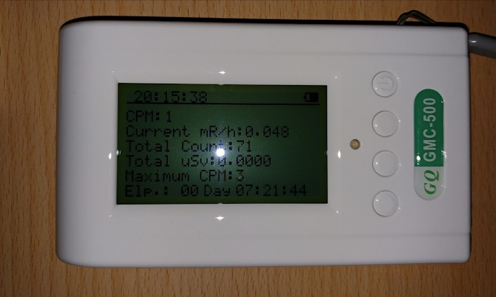
47296 bytes |
Edited by - ikerrg on 09/09/2018 11:24:43 |
|
|
| Reply #99
ikerrg
United Kingdom
334 Posts |
Posted - 09/10/2018 : 08:52:16
|
| I am now at an airport and I have just passed through security only with the si-3bg tube installed. Probably tomorrow I will show you very interesting data regarding the dose rate integration and the CPM measured with the low sensitivity tube compared to the M4011 measurement of a few weeks ago. Just to start, the si-3bg counted 228 counts in one second! Translate that to the M4011 with a sensitivity ratio of 73 and see how the HV circuit was totally saturated in the data of three weeks ago! |
|
|
| Reply #100
EmfDev
2418 Posts |
Posted - 09/10/2018 : 12:19:55
|
@ikkerg, We changed the total uSv now and should be working. Try to email support to get available firmware update.
@Stargazer. Looks like the total uSv becomes 0 after certain time.
Thank you guys! |
|
|
|
Topic |
|