| T O P I C R E V I E W |
| Stargazer 40 |
Posted - 08/25/2019 : 12:31:39
In September of 2018 I was able to review 500+ with the V2.0 PCB here:
https://www.gqelectronicsllc.com/forum/topic.asp?TOPIC_ID=5461
There were a number of hardware improvements that later firmware revisions made operational. GQ provided independent power supplies for the high sensitivity and low sensitivity tubes. The high sensitivity tube could be upgraded to allow for doubling the current available to the tube. It was found that in high count environments the tube voltage could drop out of the plateau region and even out of the Geiger Mueller zone until the voltage returned to the starting voltage for the tube. The separate power supplies, and ability to augment the current in the tube one power supply were hardware fixes. The thought was that with voltage on the V2.0 board no longer controlled by a potentiometer, but controlled by Pulse Width Modulation (PWM), that firmware control of voltage would lead to automatically maintaining the voltage at the preset level. At the time though all of the user testing effort focused on the other critical firmware add - dead time delay incorporation in counts recorded.
The workaround for adjusting voltage was to map the voltage level at the board level through DMV measurements and adjust manually by knowing the voltage change for each PWM percentage change for the specific components in the power supply. GQ provided a rudimentary change to the firmware that adjusted the PWM voltage percentage based on previous three CPS recorded automatically. This was not adequately tested at that time. The dead time delay inclusion however allowed the meters to match other commercial GMC products and was made standard.
In November of 2018 I began an effort at calibrating the GQ meters to a known standard; in this case the Mazur 9000 GCM that I borrowed from a friend, here:
https://www.gqelectronicsllc.com/forum/topic.asp?TOPIC_ID=5554
We learned a lot from that and GQ meters make use of conversion numbers and dead time delays from that effort.
When I returned to the forum after a brief hiatus in July of 2019, the primary goal was to evaluate the rudimentary firmware for automatically adjusting the voltage. Remember at that time however that I needed to make PCB level DMV measurements. It looked like a daunting task. GQ however continued to innovate and, as before, came out with new hardware. This thread by Geo-Johnny was focused on audio output, but I noticed that the PCB board was now at 5.1 from 4.1 for my 500+ meters and that there was in the upper left corner of the PCB a new component added (post #12, the white rectangle, a resistor):
https://www.gqelectronicsllc.com/forum/topic.asp?TOPIC_ID=7285
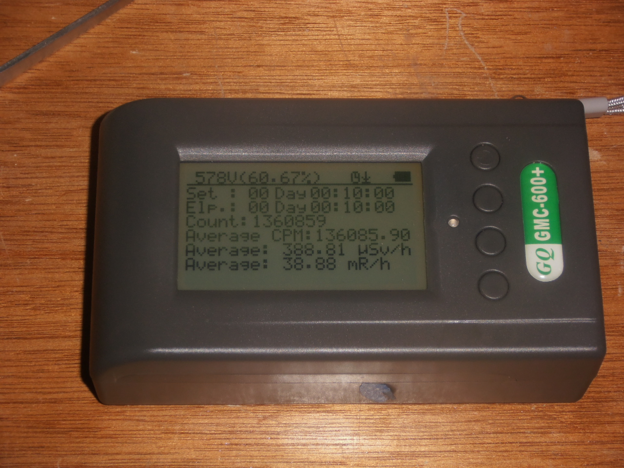
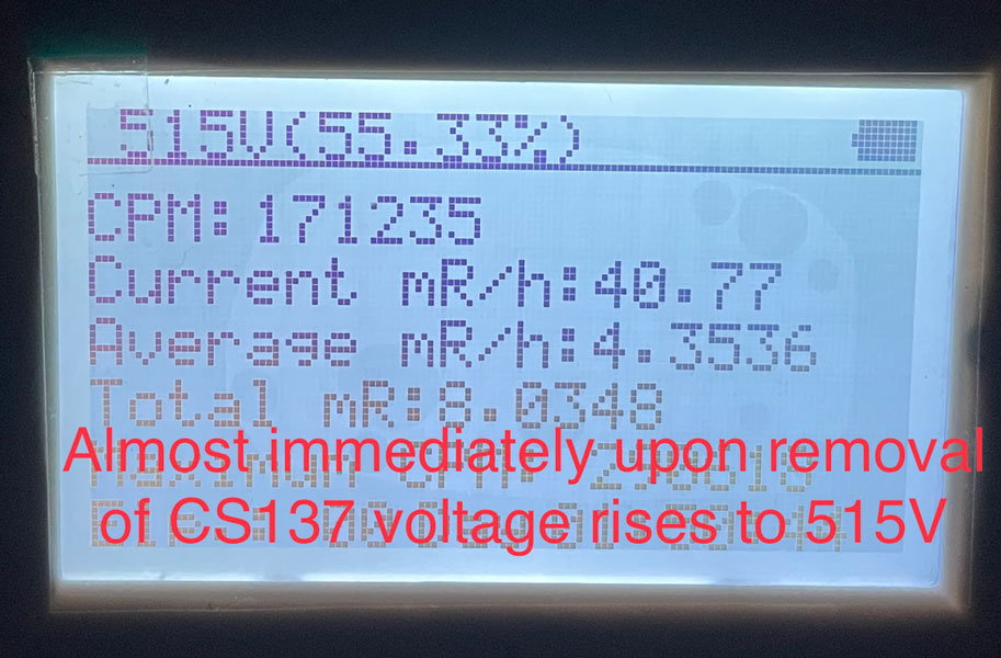
GQ had incorporated a splitter resister to allow measurement of the voltage at the tube one power supply. The rudimentary firmware still made use of percentages. With the voltage measurement hardware now in place on the PCB, the PWM percentage could be given an actual voltage for display. GQ enabled real time voltage display on the first line of the Text and Timed Count display windows (along with percentage PWM). Now I could see how the voltage acted under high CPM. See display below for real time voltage on first line.
Image Insert:
569127 bytes
Suffice it to say that the three meter types that support the AVA function (500+, 600, 600+) are all able to maintain the preset voltage while in a high count field after a brief delay while the software raises the percentage of the PWM. The least efficient GM tube (SBT-11/A) took the longest at 90 seconds to return to the preset voltage while in the field. Source was 10uCi Cs137 placed directly under the case centered on the window. We no longer need to worry about whether the tube is in the plateau region. The meter compensates very effectively with real time display of tube voltage. The user turns AVA on or off in the Tube Voltage or Tube 1 Voltage menus of the 600/+ or 500+ respectively. The user can still adjust the preset by raising with S3 or lowering with S2 when the tube voltage is displayed.
|
| 34 L A T E S T R E P L I E S (Newest First) |
| EmfDev |
Posted - 07/20/2023 : 15:51:20
Hi Janiir, currently, there is no way to turn it off. usually it is disabled when CPM is low though. |
| Janiir |
Posted - 07/20/2023 : 02:31:23
I'm new to the forum and I recently purchased a GMC 600+ and I'm not really enjoying it so far. I'm curious about the Auto Voltage Adjust feature. Also, I'm wondering if there's a way to disable the Auto Voltage Adjust feature. I'd like to be able to manually adjust the voltage, if necessary. Thanks! |
| EmfDev |
Posted - 06/28/2023 : 16:49:25
Generally this is acceptable. It has been included when calibrating. |
| Bobakman |
Posted - 06/28/2023 : 11:50:17
quote:
Originally posted by EmfDev
Hi Bob, I checked with our engineering team and said the voltage goes back to on about 15%.
Do you mean that the voltage "Dip" or decrease during higher load/high count/avalanche rate is 15% and this is acceptable is this correct?
Bob |
| EmfDev |
Posted - 06/28/2023 : 10:27:41
Hi Bob, I checked with our engineering team and said the voltage goes back to on about 15%. |
| Bobakman |
Posted - 06/28/2023 : 07:58:42
quote:
Originally posted by EmfDev
Hi Bobakman, it should go back to the original voltage but it seems the percentage is already maxed that is why the software voltage stopped to adjust. We will check this and see if we can make improvements for maintaining higher voltages in high cpm environment.
I have not heard back on this issue and am inquiring if you have addressed the power supply weaknesses?
As we all know a GM tubes reliable operation is dependent on the tubes power supply.
Having a robust designed power supply is important in the design and thus proper operation.
I almost feel that this could be classified as a design defect/oversight but not having a schematic of the power supply I am basing this only on my observations and those of others more qualified than my self.
So where do we go from here?
Bob |
| Bobakman |
Posted - 01/27/2023 : 20:59:13
quote:
Originally posted by EmfDev
Hi Bobakman, it should go back to the original voltage but it seems the percentage is already maxed that is why the software voltage stopped to adjust. We will check this and see if we can make improvements for maintaining higher voltages in high cpm environment.
Thank you Sir. I imagine if a fix is found it will be in a future firmware update?
Bob |
| EmfDev |
Posted - 01/25/2023 : 12:35:27
Hi Bobakman, it should go back to the original voltage but it seems the percentage is already maxed that is why the software voltage stopped to adjust. We will check this and see if we can make improvements for maintaining higher voltages in high cpm environment. |
| Bobakman |
Posted - 01/14/2023 : 12:11:06
Has anyone got an answer to the above question?
Thanks, Bob |
| Bobakman |
Posted - 12/25/2022 : 12:05:06
quote:
Originally posted by Stargazer 40
In September of 2018 I was able to review 500+ with the V2.0 PCB here:
https://www.gqelectronicsllc.com/forum/topic.asp?TOPIC_ID=5461
There were a number of hardware improvements that later firmware revisions made operational. GQ provided independent power supplies for the high sensitivity and low sensitivity tubes. The high sensitivity tube could be upgraded to allow for doubling the current available to the tube. It was found that in high count environments the tube voltage could drop out of the plateau region and even out of the Geiger Mueller zone until the voltage returned to the starting voltage for the tube. The separate power supplies, and ability to augment the current in the tube one power supply were hardware fixes. The thought was that with voltage on the V2.0 board no longer controlled by a potentiometer, but controlled by Pulse Width Modulation (PWM), that firmware control of voltage would lead to automatically maintaining the voltage at the preset level. At the time though all of the user testing effort focused on the other critical firmware add - dead time delay incorporation in counts recorded.
The workaround for adjusting voltage was to map the voltage level at the board level through DMV measurements and adjust manually by knowing the voltage change for each PWM percentage change for the specific components in the power supply. GQ provided a rudimentary change to the firmware that adjusted the PWM voltage percentage based on previous three CPS recorded automatically. This was not adequately tested at that time. The dead time delay inclusion however allowed the meters to match other commercial GMC products and was made standard.
In November of 2018 I began an effort at calibrating the GQ meters to a known standard; in this case the Mazur 9000 GCM that I borrowed from a friend, here:
https://www.gqelectronicsllc.com/forum/topic.asp?TOPIC_ID=5554
We learned a lot from that and GQ meters make use of conversion numbers and dead time delays from that effort.
When I returned to the forum after a brief hiatus in July of 2019, the primary goal was to evaluate the rudimentary firmware for automatically adjusting the voltage. Remember at that time however that I needed to make PCB level DMV measurements. It looked like a daunting task. GQ however continued to innovate and, as before, came out with new hardware. This thread by Geo-Johnny was focused on audio output, but I noticed that the PCB board was now at 5.1 from 4.1 for my 500+ meters and that there was in the upper left corner of the PCB a new component added (post #12, the white rectangle, a resistor):
https://www.gqelectronicsllc.com/forum/topic.asp?TOPIC_ID=7285
GQ had incorporated a splitter resister to allow measurement of the voltage at the tube one power supply. The rudimentary firmware still made use of percentages. With the voltage measurement hardware now in place on the PCB, the PWM percentage could be given an actual voltage for display. GQ enabled real time voltage display on the first line of the Text and Timed Count display windows (along with percentage PWM). Now I could see how the voltage acted under high CPM. See display below for real time voltage on first line.
Image Insert:
569127 bytes
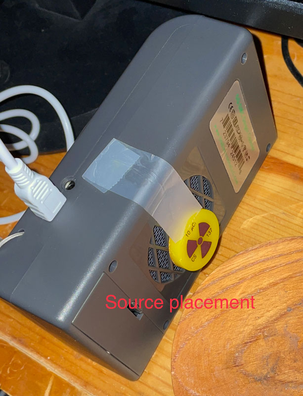
Suffice it to say that the three meter types that support the AVA function (500+, 600, 600+) are all able to maintain the preset voltage while in a high count field after a brief delay while the software raises the percentage of the PWM. The least efficient GM tube (SBT-11/A) took the longest at 90 seconds to return to the preset voltage while in the field. Source was 10uCi Cs137 placed directly under the case centered on the window. We no longer need to worry about whether the tube is in the plateau region. The meter compensates very effectively with real time display of tube voltage. The user turns AVA on or off in the Tube Voltage or Tube 1 Voltage menus of the 600/+ or 500+ respectively. The user can still adjust the preset by raising with S3 or lowering with S2 when the tube voltage is displayed.
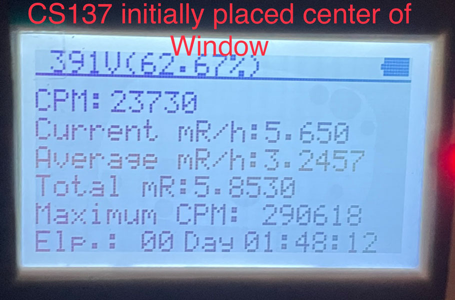
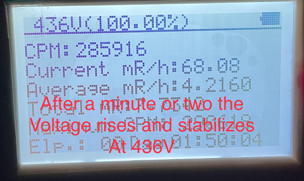
Please see images below is the voltage drop out with the indicated source 10uCi CS137
considered "Normal" for my 600+ or is it still supposed to ramp back up to the acceptable range for the
LND7317? I ask because the low end according to the LND spec sheet is 475V and mine stabilizes at 436V as indicated in the image.
Running latest Firmware 2.42
|
| mimichris |
Posted - 11/26/2022 : 23:53:23
I ordered a GMC-500, does it have the same features and settings, HT, tubes as the 500+, I think so, because the 500+ has just one more tube, correct? Thanks. |
| Damien68 |
Posted - 03/26/2021 : 01:21:12
the difference between an SBT-11 and an SBT-11A is the thickness of the mica window. this will make a difference in sensitivity for the alphas detection, for beta or gamma may be less |
| Damien68 |
Posted - 03/26/2021 : 01:05:44
what would be good is to have a table giving correction factors according to the type and elementary energy of the radiation. |
| Damien68 |
Posted - 03/26/2021 : 01:01:46
yes, in any case the measurements made will always be subject to interpretations. |
| Searinox |
Posted - 03/26/2021 : 00:56:52
This is going by that assumption yes. Energy compensation usually comes in the form of a lid which will block alpha anyway, so any open mica tube measurement will be assumed to be without compensation. The same goes for the radiation type, as a calibration against a source that gives off specific types of radiation will be off against a source giving off a much more different type of radiation. This will always be the case with a geiger unless you can selectively block the different types by yourself and check how much CPM each produces. |
| Damien68 |
Posted - 03/26/2021 : 00:44:10
do not forget that these tubes are not compensated in energy, if you calibrate it for one source, for another source, the measurement in uS/h will only be approximate around (-80% to +500%) or even (-94% to +1500%).
So the calibration factor is also a function of the nature of the radiation source. |
| Searinox |
Posted - 03/18/2021 : 13:59:11
I have the following settings on my GMC-600 with a SBT-11 tube, which I've tested to make sure they work well and stay calibrated to the sources I know as well as accurate scaling tested up to 1.5 mSv/h:
Firmware: 2.22
Voltage: 62.67%
Dead Time: 100 us
CPM: 295 for 1 uSv/h
I should also note that I actually swapped out the SBT-11A that came with the device with a SBT-11 I purchased myself separately. Interestingly enough the new tube is about 10% more sensitive, so although I feel confident vouching for the posted dead time and voltage, calibrating the CPM to uSv/h is something you'll have to each do by yourselves. But it should be somewhere in that ballpark. |
| lars.dietrich |
Posted - 01/20/2021 : 06:04:09
Hi, I have latest version 2.21 and still the following default values, which work fine for me:
Tube Voltage: 65,33%
HV Calibration: 164
Tube Dead Time: 270 microseconds
Fast Estimation time: Dynamic --> The greatest feature ever!
quote:
Originally posted by ihab17
Hello
What is the version of your current firmware on the GMC 600+?
What value did you set for the Tube Voltage?
What HV Calibration value do you use?
What is the value of the Tube Dead Time?
What is the value of your Fast Estimate Time?
Thanks
|
| ihab17 |
Posted - 01/19/2021 : 15:53:53
Hello
What is the version of your current firmware on the GMC 600+?
What value did you set for the Tube Voltage?
What HV Calibration value do you use?
What is the value of the Tube Dead Time?
What is the value of your Fast Estimate Time?
Thanks |
| Stargazer 40 |
Posted - 09/11/2019 : 09:06:26
@Damien68 - The correct version does not allow changes to the percentage change from zero to 5% step. That version did not work adequately. The newer version allows you to 'Enable' the AVA and display it on the text screens. You can adjust the tube voltage up or down in the tube voltage menu item. When the meter is moved away from a high count sample the voltage rises quickly and settles back at the set voltage. GQ is still using a three second average and 500CPS steps to adjust, and that seems a good balance for response. Only the inefficient SBT-11/A tubes in the 600 respond slowly to the adjustment. I used Scheduled with my 10 Minute Timed Counts set to two minutes to allow the meter to get back to set voltage on the 600 before starting the count. |
| Damien68 |
Posted - 09/11/2019 : 05:43:18
Hi Stargazer, Yes effectively I have same menue.
I look Tube 1 voltage to 402v (for 14% PWM), is exacly what I mesured yesterday.
I haven't see the autovoltage menu, it setted at defaut factory setting to: ' Voltage increase evry 500 CPS: 0%'
I understand than I can change it from 0 to 5%.
And I can see and change nominal tube voltage with 'Tube1 Voltage' menu.
This working fine |
| Stargazer 40 |
Posted - 09/11/2019 : 04:37:38
@Damien68 - You have restated the problem nicely. High counts load the power supply and voltage drops. That's why GQ added the Auto Voltage Adjust function. Here is a picture of the Init Setup, Tube Settings menu that shows the High Voltage Display selection. If your menu doesn't look like this then you need to upgrade your firmware. Your hardware certainly has the measuring resistor installed.
Image Insert:
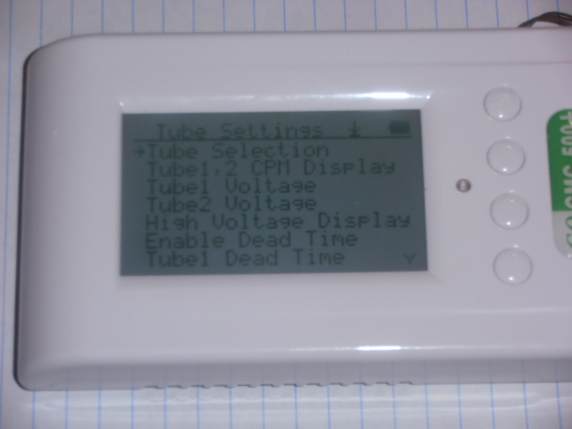
133627 bytes |
| Damien68 |
Posted - 09/10/2019 : 23:43:01
GMC-500+
SN: XXXXXXXXXXXXXX
HW: GMC6 v5.2
SW: v2.14 |
| EmfDev |
Posted - 09/10/2019 : 13:02:48
Damien68 what version of firmware do you have? |
| Damien68 |
Posted - 09/10/2019 : 12:43:25
As for the voltage adjustment for the high sensitivity tube, on my 500+ I noticed one thing:
The voltage applied to the tube (at least on its anode resistance) is a function of the 'PWM' ratio defined by the software: it works.
The voltage on the tube is measured using an ohmic divider (1Gohm / 5Mohm) goes into a follower AOP and is returned to the microcontroller (analog input certainly): it works and the better way to measure the tube voltage is to measure the voltage at the AOP output and multiply it by 201.
But when I load the HT generator by placing a load on it, I see his voltage output to drop, it may be normal but we see no reaction of microcontroller. (No change of the PWM duty cycle, no change of the frequency either (observed on the transistor gate charging the inverting inductance.
So the Microcontrolleur adjust the tube voltage but don't regulate it.
it could do it, even if it is not in ideal conditions because of the delay imposed by the sampling, the call of ISR functions, the treatment and the adjustment of the PWM,... It is all that it is necessary to create instability, but which can be corrected by a good 'PI' filter (Proportionel - Integrale).
At least all this is the interpretation I made of my measurements (looking for something else)
In any case, however, aparently the voltage applied to the tube is for the moment not reguled, and is simply a balance between different capacitances, an inductance and values of different leakage currents, ..., and of course PWM setting.
After that there may be some compensation with the previous CPM or CPS values,
In this case in my measurements I would not have seen them. But it seems not necessarily very stable.
It does not prevent the GMC-500 + from working well, but he could display the real voltage of the tube, he knows it :) |
| Geo-Johnny |
Posted - 08/27/2019 : 05:59:07
Yup, I saw, that's why I want it too.  |
| Stargazer 40 |
Posted - 08/27/2019 : 02:20:50
You may have seen my addition of an LND712 wand to one of my 500+ here
http://www.gqelectronicsllc.com/forum/topic.asp?TOPIC_ID=5416
Probably the best of the end window alpha, beta, gamma tubes |
| Geo-Johnny |
Posted - 08/26/2019 : 23:24:48
Thank you Stargazer_40 for the detailed description. Yes, it is an interesting but also dangerous hobby. I'm almost 60 years old and I'm mainly interested in the electronics for the devices. I now have good contact with EmfDev and I am patiently waiting for new updates. You're right, the GMC500+ is GQ Electronics' best all-rounder. So I want to buy a second GMC500+ and swap the M4011 tube for a LND712 tube. With the voltage settings, the GMC500+ is great for experimenting. |
| Stargazer 40 |
Posted - 08/26/2019 : 15:51:15
@Geo-Johnny, Thank you for being concerned about my health. I am a cancer survivor and during testing associated with that I had four PET scans over two years. Each is equivalent to two rads exposure. I worry a little about lung cancer from those, but it has been fourteen years so don't worry much anymore. :-)
I do have great respect for the sources I use in my testing. They are considered educational level in the US. They may be sent through the mail unprotected in a large box. Their intensity is really point source. I have never touched one. I have 15" aquarium tongs that I move them about with. I have lead cylinders called 'pigs'. I store them in those in the far reaches of my basement. That cuts everything but gammas, and those are down about 50%. For Cs137 gammas are only about 10% of output IIRC. I am using Timed Count testing now and leave the area while the meter records. Left the area whenever I was waiting for meter to settle on previous measurements. I am concerned for fire and law enforcement first responders in Hazmat situations. We forget that serious harm begins at about 5R/h with possible chromosomal damage. That wouldn't detour most first responders. They wouldn't turn back (when lives are in danger) until 40R/h exposure is reached. For our 600 meters we go well past the Mazur 9000 meter limits (1250uSv/h). That's .14R/h. So really we only have canaries in coal mines with these meters. If something sets off an alarm we should probably see what's different or go somewhere else. The SI3BG tube in the 500+ that I call a survey tube is the one we really need to pay attention to in a crisis situation. It is primarily a gamma detector and is capable of reaching 40-60R/h. That's when you don't want to be there. And really that's why I think the 500+ is the best value of the GQ lineup (covers a broad range). I have three of them. |
| Geo-Johnny |
Posted - 08/26/2019 : 12:25:13
Yes that is true. Stargazer_40 does a great job, thank you also from my side. But sometimes I worry about his health. The radiation samples already have very dangerous high values. I hope he pays attention to his self-protection! |
| EmfDev |
Posted - 08/26/2019 : 12:07:30
@Stargazer_40, thank you so much for your efforts! We greatly appreciate your testing and hard work on improving the GMC units. |
| Geo-Johnny |
Posted - 08/26/2019 : 06:04:22
Ohhh, I got in touch with support just last week and got a new firmware for the GMC500+. I have Rev. 2.13 as the newest.
Anyway, I'll write to the support again. Thank you very much, it is very interesting. |
| Stargazer 40 |
Posted - 08/26/2019 : 03:48:37
This will require a firmware upgrade. Please contact support@gqelectronicsllc.com |
| Geo-Johnny |
Posted - 08/26/2019 : 00:48:27
Thanks for the great information. I understand well what it's about, but I do not know how to get the counter tube voltage displayed on the text screen by my GMC500+ ?
It would generally be urgent for GQ Electronics to revise the Usermanuals and explain the new menu features in detail. Or for these new menu entries a supplement text in pdf format provides.
|