| T O P I C R E V I E W |
| Geo-Johnny |
Posted - 07/17/2019 : 04:35:46
The "Third Party Output" switch in the "Others" menu has absolutely no function. It does not matter if ON or OFF the audio pulses are always output. Only when the speaker is switched off, no pulses are output via the audio interface. I think that is a bug in the firmware? My GMC 500+ has the revision number Re2.12.
Please, maybe another user can check and confirm this with his GMC 500+?
Regards ...
Johnny |
| 34 L A T E S T R E P L I E S (Newest First) |
| Damien68 |
Posted - 08/25/2019 : 03:07:07
yes it's correct, for my part, I do not find the necessary of orange light. it's just to understand. |
| Geo-Johnny |
Posted - 08/25/2019 : 01:10:13
That's right, but just to make the diode shine orange, the layout change and the effort with two resistors is too big. The GMC320+V5 was then solved with two resistors,by the GMC500+ is just one resistor. |
| Damien68 |
Posted - 08/24/2019 : 22:42:07
Hi,
when the two anodes of the LEDs (red + green) are high, it is normal for the led to remain flashing red, because the red diode has a lower voltage than the green diode and therefore takes all the current that passes through R20. In order for the LED to light up in orange, it would have been necessary to place two resistors (one for the red anode and another one for the green one). |
| Geo-Johnny |
Posted - 07/25/2019 : 21:08:06
No, the LED only responds to the counts as intended. But my modification brings a clean audio signal at all times, even if the LED or speaker is turned off by the user in the settings. The GMC 500+ audio output works perfectly now.
|
| Stargazer 40 |
Posted - 07/25/2019 : 16:06:35
Yes, I was asking about your modification. So the LED doesn't react at all to the pulses from the audio circuit.
|
| Geo-Johnny |
Posted - 07/25/2019 : 11:56:43
quote:
Originally posted by Stargazer 40
So what happens when a click comes through to the LEDs when this modification has been made? Do they both blink or ??????????????
Wich modification you mean? If you mean my solution with the audio output, this has no influence on the LED. |
| Geo-Johnny |
Posted - 07/25/2019 : 11:49:47
quote:
Originally posted by EmfDev
That is coded that way. Both terminals are set to 'High' already when CPM is in medium default is 51-100? But The Red dominates that's why we just see red instead of orange.
Okay, then we can nothing do. It is not importent, it is just cosmetic. Important is the change from green to red, thats enough. |
| Stargazer 40 |
Posted - 07/25/2019 : 11:01:16
So what happens when a click comes through to the LEDs when this modification has been made? Do they both blink or ?????????????? |
| EmfDev |
Posted - 07/25/2019 : 10:38:17
That is coded that way. Both terminals are set to 'High' already when CPM is in medium default is 51-100? But The Red dominates that's why we just see red instead of orange. |
| Geo-Johnny |
Posted - 07/25/2019 : 09:50:38
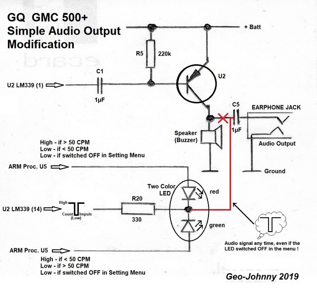
Incidentally, when I look at my drawing, I think of a cosmetic firmware option. From 51 to 99 CPM, the CPU could set both anodes of the LED to High Signal. Then the LED would light orange at medium level. Because green and red together make an orange light.
It's just an idea of mine, but a cosmetic top idea, because programming would be very easy.
Best regards from overseas ...
Johnny
Edit: Upps, you was faster.  |
| EmfDev |
Posted - 07/25/2019 : 09:46:45
Alright thank you so much! Looks correct. There's supposed to be an orange color when CPM is in Medium range from 50-100 where both LEDs are High but it just becomes red. |
| Geo-Johnny |
Posted - 07/25/2019 : 06:53:52
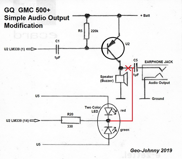
Listen, my english ist not the best. So i try it with a corrected picture.
I hope now it is not so hard to understand? |
| EmfDev |
Posted - 07/24/2019 : 09:55:46
It's just so hard to understand. |
| Geo-Johnny |
Posted - 07/23/2019 : 22:33:37
quote:
Originally posted by EmfDev
So it still works even if you turn off LED in the options?
Yes, I am surprised, but it also works when the LED is turned off. I have a guess, but I did not have time to measure it. When I have time, I will find out why it is. |
| EmfDev |
Posted - 07/23/2019 : 14:35:02
Ohh I see, thanks for explaining. So it still works even if you turn off LED in the options? |
| Geo-Johnny |
Posted - 07/23/2019 : 14:13:14
That is not completely right. The middle pin of the LED is negative but not ground !!! Before that is R20 with 330 ohms and that's the trick. The plus signal comes via the (two) LED's to the middle pin (cathode). At the moment of the impulse, this point is positive (high), because the internal resistance of the diodes is much smaller than the 330 ohms. Can you follow me? |
| EmfDev |
Posted - 07/23/2019 : 13:50:50
It's good as long as it works! Although I can't figure out how it worked. Haha. The middle pin is ground. |
| Geo-Johnny |
Posted - 07/23/2019 : 13:16:34
@EmfDev
What does your engineer say about my unprofessional amateur modification? |
| EmfDev |
Posted - 07/22/2019 : 15:53:24
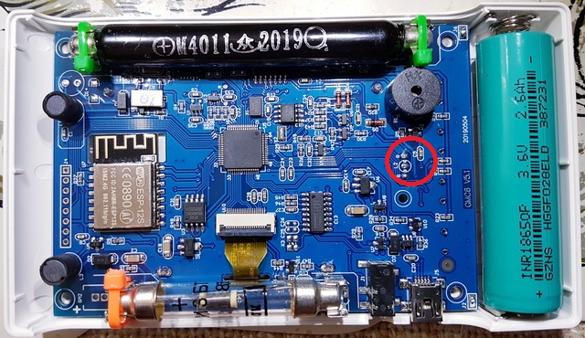
Stargazer_40, 5.1 is the latest PCB version and it has capability to display the real tube voltage(tube 1) on the screen.
If you have questions please email support. |
| Stargazer 40 |
Posted - 07/22/2019 : 13:35:28
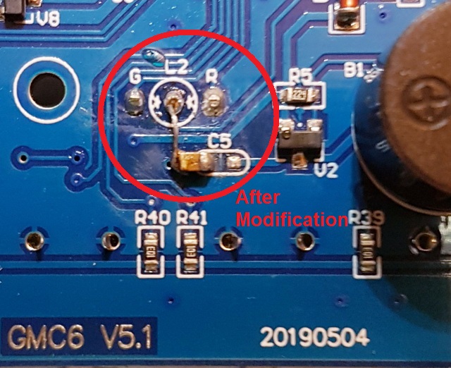
Thank you for sharing this. I see GQ has upgraded the PCB board to version 5.1 and it is now GMC6 as 'model number'. The part you modified is same for the 4.1 PCB board. I don't want to steal this thread, but would like to know what changes went into 5.1 from 4.1? I notice just below the (+) on the M4011 tube in first picture above a white rectangle that is folded over the PS transistors. Is the board just simplified or other capability added? Thanks! |
| Geo-Johnny |
Posted - 07/22/2019 : 12:19:29
quote:
Originally posted by ZLM
Good work!
Thank you for sharing. This part should be improved from GQ.
Thank you for the flowers. It's certainly not a professional solution, but it works very well for my needs. The GMC 500+ is brand new, I did not want to destroy anything and i was looking for the simplest solution. Sure, there are better solutions with triggered output, etc., but for me it's enough. Previously, you could not even press a button, because it was immediately triggered several false impulses, a horror, that got on my nerves. |
| ZLM |
Posted - 07/22/2019 : 10:02:31
Good work!
Thank you for sharing. This part should be improved from GQ. |
| Geo-Johnny |
Posted - 07/21/2019 : 02:54:59
quote:
Originally posted by EmfDev
Yes you can make a separate thread for this one.
No, i think the modification is so simple that no need a own thread.
And, pictures say more than 1000 words.
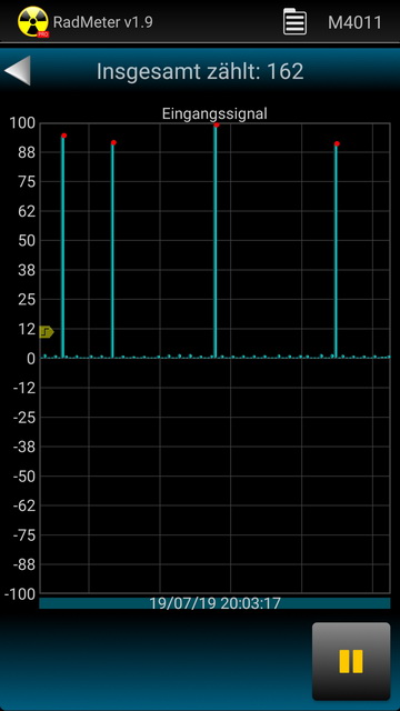
Screenshot from the Android App "RadMeter Pro" (soft inverted Input!) |
| EmfDev |
Posted - 07/19/2019 : 14:43:25
Yes you can make a separate thread for this one. I don't understand what you did yet just removing the C5 capasitor and connecting it to ground?
We can try you way on Monday to see if it does indeed work and can't cause any problems. |
| Geo-Johnny |
Posted - 07/19/2019 : 13:08:29
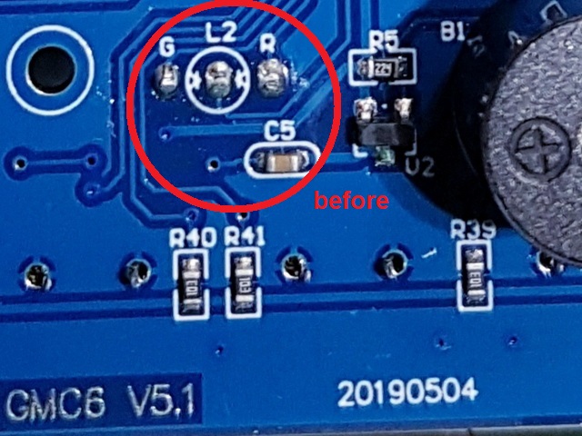
Sorry, I probably translated that badly, but now I understand everything your engineer means. To mechanically switch off the loudspeaker via the headphone jack would be too complicated a solution to the problem. It would not be the best either. I have now found a very simple solution and it works perfectly. The original wiring of the audio signal runs from the speaker via a 1uF (C5) condenser to the headphone jack. This is a very bad solution because the loudspeaker works as a microphone and emits every key press or knock on the housing as a pulse, which results in a wrong count on the subsequent device. I have soldered out the C5 capacitor on one side and connected to the common cathode of the two-color LED. The LED is 5mm away from C5. Here comes a clean impulse for the audio output and it works great. I can turn the speaker on or off and there are no false impulses when touching the case. To my great pleasure you can also turn the LED on and off and the count spikes come anyway.
If interested, I can open a separate thread showing the layout change with photos and a partial schematic of the change. There is also a screenshot of the Count Impulse from the Android app. If someone can solder SMD, the change takes five minutes. All you need is 5mm thin wire.
Best regards ...
JOHNNY |
| EmfDev |
Posted - 07/18/2019 : 08:56:32
Sorry I didn't explain it more clearly. Our engineer suggested that you can modify the hardware by damaging the PCB so that you don't need to hear the loud speaker sound when you connect an audio cable. Even if the speaker setting is 'ON' you won't be able to hear it if connected to an audio cable. It will automatically turn off the hardware speaker sound. But that is hard because it's going to damage the PCB in the current HW. |
| Geo-Johnny |
Posted - 07/18/2019 : 05:21:30
Sorry, but your engineer is not right, because the speaker can be turned on and off via the software. This has nothing to do if the device is connected to the microphone input of a headphone jack from a smartphone or to a computer. You can turn on or off the loudspeaker at the Geiger counter at any time. That is not the problem. The problem with the GMC-500+ is, that the software also cuts off the audio signal when the loudspeaker is switched off. That's not comfortable, but no matter, maybe I'll find a solution myself. With the GMC-320+ V5, the audio output is always on, regardless of the speaker. This works great with the Android app "Radmeter" together.
Nevertheless, I thank you very much for your efforts and send you best regards from Vienna / Austria. |
| EmfDev |
Posted - 07/17/2019 : 14:07:59
I asked our engineer and he said that it's possible to turn off the speaker while a audio cable is plugged in but you are going to damage the PCB. So it's not recommended. It was designed like this because it was not meant to turn off the speaker while connected to an analog receiver or connect to an earphone to listening to the count. |
| Geo-Johnny |
Posted - 07/17/2019 : 12:47:55
Ok, thanks.
If it's a hardware issue, that's not good news for me. But I am practicing soldering in the SMD and maybe there is a solution for the existing board, by bridging or interrupting a track. Without a schematic it is a little difficult for me. I'm surprised what your engineer says. |
| EmfDev |
Posted - 07/17/2019 : 12:17:27
It's possible there might be a new hardware change for that one. I'll let our hardware engineer know about this design. |
| Geo-Johnny |
Posted - 07/17/2019 : 11:19:42
Thank you for the enlightening words, now everything is clear. Will there be firmware updates for the GMC-500+ devices, especially for the second generation in the future? For example, especially for this speaker Audioport switching problem? |
| EmfDev |
Posted - 07/17/2019 : 10:58:14
Sorry about that, we forgot to add them into the user manual. The hardware design for 500/+ are different. Yes the speaker also shouldn't turn off the analog pulses from the audio port.
The auto voltage regulator adjusts the voltage of the device depending on the count because the voltage between the tube decrease if the CPM is too high say 30000CPM. |
| Geo-Johnny |
Posted - 07/17/2019 : 10:31:07
Thanks for the information, but unfortunately I found nothing in the manual. I also do not understand why the speaker must be turned on, so come out at the audio port signals? With the GMC 320 + V5 it does not matter whether the loudspeaker is switched on or off.
In general, there are menu items that are not in the manual of the GMC 500+. For example, I do not understand the menu item for the auto voltage of the counter tubes? The separate manual tension adjustment for the two counter tubes is clear to me. |
| EmfDev |
Posted - 07/17/2019 : 10:12:04
The third party output has nothing to do with the audio pulses. It outputs 0xFF for every count in the comport. |