| T O P I C R E V I E W |
| franco |
Posted - 08/18/2011 : 13:15:33
I am interested in modifying the kit slightly. I wanted to power the kit with my own supply. Is there a range of operating voltages that can be fed to the board? Say 7v-15vdc or does it have to be 9v. Also if I wanted to take TTL output from the board could I simply lift the LED and tie that to a microcontroller? |
| 8 L A T E S T R E P L I E S (Newest First) |
| ZLM |
Posted - 09/17/2011 : 13:39:34
The software want to see a sharp wave for each click. So, I think the first one is the better one. |
| Odiez1 |
Posted - 09/16/2011 : 13:07:37
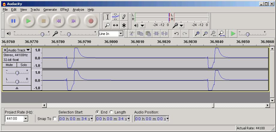
Here's what I've gotten through the Line In on my computer..
Is this the normal wave? I moved the volume slider for the Line In to just below the 3rd tick from the bottom to get a peak at the top and bottom.. Above the 3rd volume tick mark it squares off the top and bottom of the wave..
Image Insert:
75.36 KB
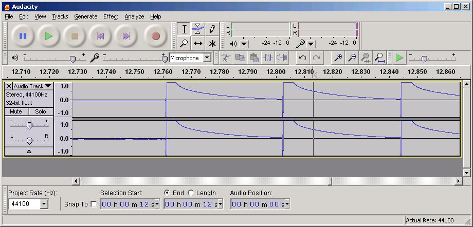
It seems like the signal is way too loud for a mic input to me.. On the Mic In it was way over modulated, but that may be what the software wants to 'see'. Here's the Mic Input with the volume slider all the way up, where I've had it before..
Image Insert:
78.95 KB
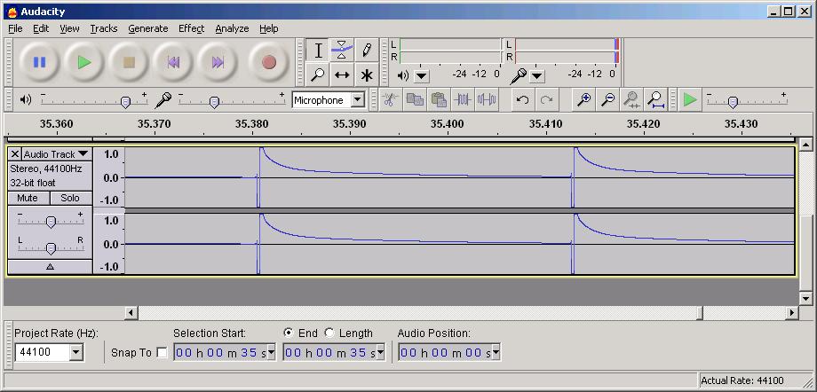
Here's a pic from the Mic In level set about where it was on the first pic for the Line In.
Image Insert:
77.62 KB
Which of these are the best wave for the software to detect?
Thanks.  |
| ZLM |
Posted - 08/24/2011 : 15:07:20
That is the correct wave. It will work with your 3.3V MCU.
This diode only limit the voltage, not correct the wave. If you want a nice look square wave, then you may need extra circuit to correct it. Just use a simple 74C04 will do the job.
If you want to use in on your 5V TTL MCU, change your diode to 4.8V. |
| franco |
Posted - 08/23/2011 : 06:47:20
I followed your directions and removed the diodes and added a 3.3v Zener cause I'm tying to the input of a 3.3v MCU. But the waveform I'm getting has me concerned. Please see pic. What can be done to clean this up for sending to the MCU?
Image Insert:
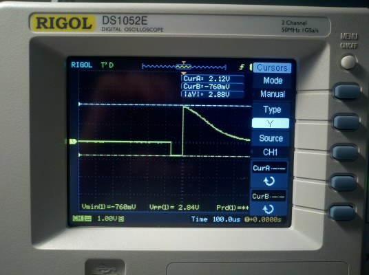
45.53 KB |
| ZLM |
Posted - 08/20/2011 : 20:00:06
You ucan try to connect GMC-080 data port to your TTL circuit, most likely it works. If it does not work, then you need to remove D6 and D7 on the PCB, and solder a 3.6V to 4.8V zener diode instead.
Remove D6, D7 diode

49.33ĀKB
put a 4.8V zener diode in this way
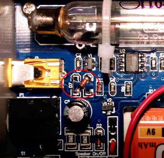
49.18ĀKB |
| franco |
Posted - 08/19/2011 : 12:04:57
Thanks for the info. Any chance of getting a schematic for the board? |
| duxzero |
Posted - 08/19/2011 : 09:03:27
Could you please draw a quick sketch on how to grab a TTL signal (without noise) from the PCB without touching the audio output? |
| ZLM |
Posted - 08/18/2011 : 15:19:57
The power supply can be 7~12V. out of this range is not recommanded.
The data port voltage level is limited to 0~1.4V. It is not TTL compatible. If you want TTL level, you can remove two diode on port and parallel a 4.8V zener diode on data out put port. That is the simplest way I have. |