| T O P I C R E V I E W |
| ullix |
Posted - 08/11/2018 : 05:09:20
GQ has generously supplied me with GMC-500+ counter for testing, and I am running it through its paces.
First I wanted to make sure that GeigerLog supports all the new features, and so far the new GL version 0.9.08 does all of that! (not yet released, but a release candidate can be downloaded from the testing folder on the GeigerLog site, https://sourceforge.net/projects/geigerlog/ )
Not bad for a blind development (well, not quite, because user the_Mike was very helpful with his eyes on his 500 counter, thanks!).
The new case is only slightly larger than that of the old 300 counters, but seems more sturdy and in a more modern design than the old, boxy cases. The buttons are also improved, but I doubt I will ever become a friend of the button concept of the counters. The display is about twice as large and much easier to read, though it does seem to have only the same resolution (dots-per-inch) as the old ones. Which, however, suffices.
The display adjusts itself for proper reading from top to bottom when you hold the counter with its buttons to the left, to the bottom, or to the right - quite convenient. But, strangely, not when the buttons are pointing to the top. (A bug?)
The display shows CPM, CPM1st tube, CPM2nd tube, well readable. CPM is the sum of CPM1st and CPM2nd.
Hmmm. From all possible things one can do with the CPM1st and CPM2nd counts, showing the sum of them is the least meaningful. Even if these were two identical tubes!
My suggestion: scrap the CPM completely and only show 1st and 2nd! Then in a bigger font.
And while you're at it: the unit "Roentgen" had been deprecated some 40 years ago and replaced by Sievert. Is 4 decades not enough for GQ to follow suit? Removing it has the advantage of saving real estate on the display, which could be used for �Sv/h for the 2nd tube.
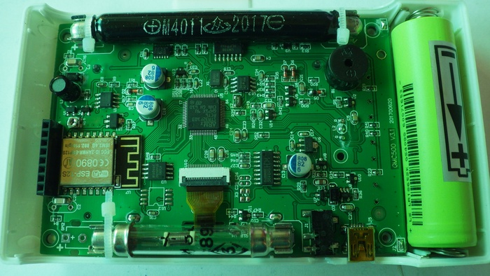
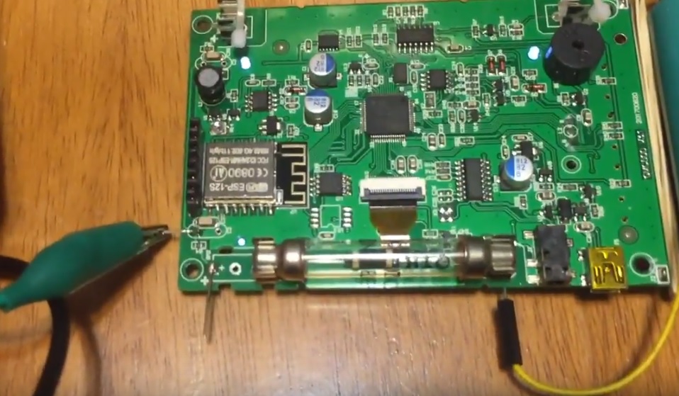
I removed the backplate (4 easy screws) and found a surprise:
Image Insert:
485275 bytes
The M4011 had been a tube of clear glass, and you could see some rainbow colors probably from internally evaporated metals. It is now a tube encased in what seems to be a black plastic cover. Perhaps the consequence of light-sensitivity which I had observed earlier? http://www.gqelectronicsllc.com/forum/topic.asp?TOPIC_ID=4540 Based on limited experiments, so far it does not seem to have a negative impact.
Do other GMC-500(+) owner also have black tubes?
One problem: the name as printed on the tube remains 'M4011'. Be aware of potential confusion when you shop for M4011!
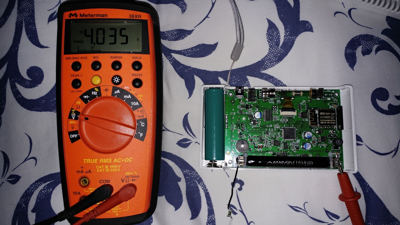
The counter has only a single High-Voltage (HV) generator, so both tubes must live from the same voltage. I used a good Digital Multimeter (6000 counts) with 10MOhm internal resistance and a 1 GigaOhm precision (1%) resistor in series. This means I will measure a voltage, let's say 4.000V, and must multiply with (1000 + 10) / 10 = 101 to get a true voltage of 404V.
I measured a slightly fluctuating voltage of 376...379 V. This voltage is low, even below the recommended operating range according to some websites. For comparison I measured voltage at M4011 of my 300E+ counter and got 395V.
Is below 380V really the intended voltage?
The problem I can see is that with increasing count rate, the current drawn from the HV increases, and due to the high internal resistance of the HV source, the voltage will decrease further. You can see this effect by measuring the voltage without the 1GOhm resistor directly in the 1000V range of the DMM. Instead of 376...379V it will show only 133V; this is normal.
But when you start at the bottom end of the working voltage, any further decrease will get you out of the operating range, which is particularly bad for a device built with a 2nd tube intended for exactly those conditions where it might not work any more?
Please, clarify the situation.
|
| 100 L A T E S T R E P L I E S (Newest First) |
| ullix |
Posted - 08/22/2023 : 02:24:23
The wrapping of the tube is supposed to eliminate the light-sensitivity of these glass tubes. Search in the forum, you will find plenty of light-sensitivity-problems discussions.
You can also look into the GeigerLog manual and read chapter "Appendix H � Light Sensitivity of Glass Geiger Tubes" https://sourceforge.net/projects/geigerlog/files/
Yes, that wrapping will take away some of the sensitivity of the tubes. Mainly beta radiation will be affected. But removing the wrapping may result is a useless Geiger unless you also use it during complete darkness ;-))
|
| chrism |
Posted - 08/21/2023 : 03:02:36
Same here, Board says GMC6 V5.4 and both tubes seem to be shrink-wrapped somehow. Is there a way for me to identify which tubes are in there? While I assume the shrink wrap protects the glass tubes, will it also shield some of the radiation? |
| Dsl71 |
Posted - 08/15/2023 : 03:31:42
Hmm mine looks like this:
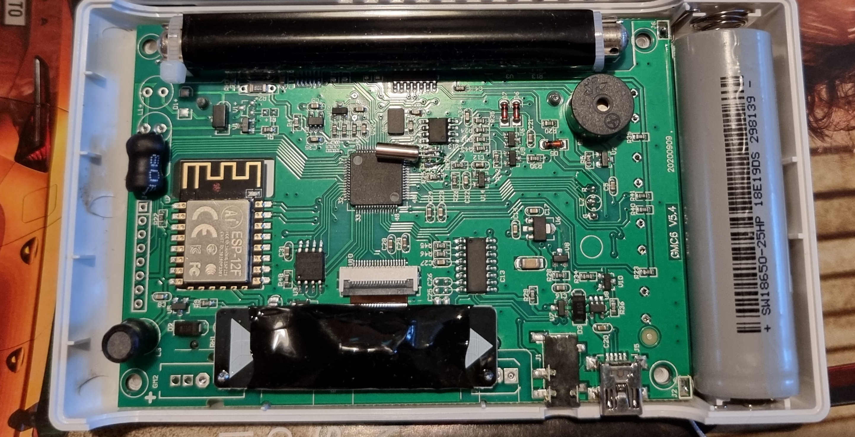
Purchased in 5/2023
It has board revision 5.4 from 20200909. I also have the 600+, it uses the same board revision, only some parts are different. |
| raleigh_littles |
Posted - 08/11/2023 : 14:18:25
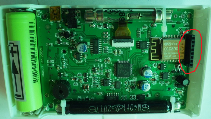
On the left side of your picture (opposite side of the battery), there's an 8-pin connector -- what is this connector for?
quote:
Originally posted by ullix
GQ has generously supplied me with GMC-500+ counter for testing, and I am running it through its paces.
First I wanted to make sure that GeigerLog supports all the new features, and so far the new GL version 0.9.08 does all of that! (not yet released, but a release candidate can be downloaded from the testing folder on the GeigerLog site, https://sourceforge.net/projects/geigerlog/ )
Not bad for a blind development (well, not quite, because user the_Mike was very helpful with his eyes on his 500 counter, thanks!).
The new case is only slightly larger than that of the old 300 counters, but seems more sturdy and in a more modern design than the old, boxy cases. The buttons are also improved, but I doubt I will ever become a friend of the button concept of the counters. The display is about twice as large and much easier to read, though it does seem to have only the same resolution (dots-per-inch) as the old ones. Which, however, suffices.
The display adjusts itself for proper reading from top to bottom when you hold the counter with its buttons to the left, to the bottom, or to the right - quite convenient. But, strangely, not when the buttons are pointing to the top. (A bug?)
The display shows CPM, CPM1st tube, CPM2nd tube, well readable. CPM is the sum of CPM1st and CPM2nd.
Hmmm. From all possible things one can do with the CPM1st and CPM2nd counts, showing the sum of them is the least meaningful. Even if these were two identical tubes!
My suggestion: scrap the CPM completely and only show 1st and 2nd! Then in a bigger font.
And while you're at it: the unit "Roentgen" had been deprecated some 40 years ago and replaced by Sievert. Is 4 decades not enough for GQ to follow suit? Removing it has the advantage of saving real estate on the display, which could be used for �Sv/h for the 2nd tube.
I removed the backplate (4 easy screws) and found a surprise:
Image Insert:
485275 bytes
The M4011 had been a tube of clear glass, and you could see some rainbow colors probably from internally evaporated metals. It is now a tube encased in what seems to be a black plastic cover. Perhaps the consequence of light-sensitivity which I had observed earlier? http://www.gqelectronicsllc.com/forum/topic.asp?TOPIC_ID=4540 Based on limited experiments, so far it does not seem to have a negative impact.
Do other GMC-500(+) owner also have black tubes?
One problem: the name as printed on the tube remains 'M4011'. Be aware of potential confusion when you shop for M4011!
The counter has only a single High-Voltage (HV) generator, so both tubes must live from the same voltage. I used a good Digital Multimeter (6000 counts) with 10MOhm internal resistance and a 1 GigaOhm precision (1%) resistor in series. This means I will measure a voltage, let's say 4.000V, and must multiply with (1000 + 10) / 10 = 101 to get a true voltage of 404V.
I measured a slightly fluctuating voltage of 376...379 V. This voltage is low, even below the recommended operating range according to some websites. For comparison I measured voltage at M4011 of my 300E+ counter and got 395V.
Is below 380V really the intended voltage?
The problem I can see is that with increasing count rate, the current drawn from the HV increases, and due to the high internal resistance of the HV source, the voltage will decrease further. You can see this effect by measuring the voltage without the 1GOhm resistor directly in the 1000V range of the DMM. Instead of 376...379V it will show only 133V; this is normal.
But when you start at the bottom end of the working voltage, any further decrease will get you out of the operating range, which is particularly bad for a device built with a 2nd tube intended for exactly those conditions where it might not work any more?
Please, clarify the situation.
|
| Damien68 |
Posted - 08/11/2020 : 22:25:18
I have the same thing, I think it's normal, it must be the anode (metal strand) of one of the two tubes which must move inside its insulator standoff |
| rfranco |
Posted - 08/11/2020 : 18:15:32
I just got the 500+ and there is something inside that sounds like a spring when you shake it even a little. Could that sound be coming from the SI3BG tube? |
| Damien68 |
Posted - 10/04/2019 : 09:00:45
The only voltage that counts towards the specifications of the tube is V(AC) (voltage between point A and Point C).
When the tube does not detect particles:
it's impedance is almost infinite. no current flows through it, it only equivalent to a capacitive load of a few pF (6-10pF).
So in this case V(AC)=V(BC)
When the tube receive a particles:
his impedance drop around 0 ohms (like a shortcut), the anode resistor is here to limit the current and partly to stop the electric arc created in the tube.
So when tube receive particle, V(BC) drop near to 0v if you add 1G ohm resistor to oscilloscope probe, you can't see this easyly because the oscilloscope probe capacitance and the 1Gohms added resistor make a RC low pass network that cutting the transient.
HV generator of 500+ don't realy have impedance, the voltage delivered is a balance between Inductor value, mainly parasitic capacitance (diode, inductor, ...), it's also in balance with Power supply voltage , PWM frequency, PWM duty cycle, transistor caracteristics and global leakage current (in large part due to 1Gohms resistor for internal voltage probe). this last one is importante to ensure in part the stability of voltage.
So first think to know is if you have low battery:
Full LiON battery deliver 4v2.
Nominal (middle charged battery) deliver 3v7
Low batterie deliver around 2v8
If battery voltage drop under 3v3, the internal 3v3 voltage regulator is no longer effective and HV voltage drop. this is not observalble on displayed voltage because the processor reference voltage used to measure HV voltage decline also in same proportions.
So Don't use 500 with low battery under 3v3 (but it is very end of life).
When receive high CPM, the tube change the balance of the High voltage generator, so there is software compensation to boost it and find a correct balance. I think it's okay.
there may also be software ajustments on CPM's count which could satisfactorily compensate any weaknesses from the HV generator (at the same time as compensating the natural blind time of the tube)
After all, it important to understand the system correctly (it is more complex than that) and as we are in a very statistical environment, we can mathematically modeling and compensate.
but do not make too hasty conclusions.
|
| Stargazer 40 |
Posted - 10/13/2018 : 05:01:01
quote:
Originally posted by ullix
Calibration Factors
While the calibration factor of 0.0065 �Sv/h/CPM for the 1st tube, the M4011, has been taken for granted (without any data ever presented to support this claim) the calibration factor for the 2nd tube, the SI3BG, remains elusive, even as a factor relative to the 1st tube.
All evidence available suggests that it is higher than the claimed 0.194 �Sv/h/CPM, meaning its sensitivity is not only 30time less than the 1st tube, but 60, 100 or even 500 times less!
Actually in the sticky 'For those wishing to calibrate their unit' at the top of the forum list, Alchemy2 goes through calibration of the M4011 and SBT-11A tubes in his GMC-320+ meters in quite a lot of detail (including shielding for betas).
The average between the three types of sources he used (Cs137, Ba133, Co60) for the M4011 tube is 154.33 CPM over background and rounded to four decimal places is .0065 CPM/uSv/hr.
This appears to be a pretty good plan to follow if you have the sources. Still want to acquire the additional source types at 5 uCi levels, except Co60, which is only available at 1 uCi level and will go through this exercise, but since I do have the Cs137 already it will be straight forward to redo now for the single source.
As for the SI3BG tube I found specs at this site
h**ps://picclick.ca/NEW-SI-3-BG-SI3BG-CI3BG-192146574795.html
Gamma sensitivities of 1.13 - 1.41 CPM/uSv/h (these are same as ikerrg found using his Russian keyboard for the Russian spec sheet in the SI3BG thread) or
.709 - .885 for conversion factor to uSv/h. With an average of .797 the 25 CPM 3rd calibration point would be 19.93.
GQ, this is additional confirmed documented information on the SI3BG tube (and that fits much better data ullix, ikerrg and I have posted) and now should justify the change of conversion factor programmed by GQ as shipped from .194 up to something like .797 (M4011 is 123X more sensitive). It's a gamma sensitivity, but at levels the tube will be used at that's all that matters. The limit of measurement for the SI3BG tube is 300 R/h. That's well into Severe Radiation Sickness, Likely Fatal.
|
| ikerrg |
Posted - 09/14/2018 : 12:37:57
Thanks for the info. I may increase it a bit more. |
| Stargazer 40 |
Posted - 09/14/2018 : 11:52:00
I set mine to 440V, which was the top of the plateau. The meter seems to be working fine.
|
| ikerrg |
Posted - 09/14/2018 : 11:13:45
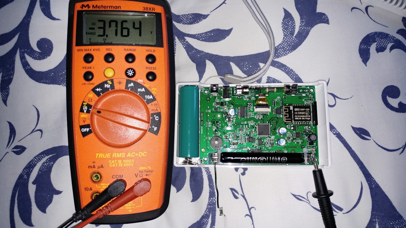
I have just received a 1 GOhm resistor (by the way SMD type because it was much cheaper!) and I have measured the stock voltage of my GMC-500+. The DVM reading was 3.764 V, which corresponds to a voltage in the tube (with the DVM connected) of about 380.2 V, which should rise to 387.4 V when the DVM is disconnected (I used the internal resistance of the HV circuit given by ullix in this thread, i.e. 16.12 MOhm).
Image Insert:
283532 bytes
I have changed the default voltage so the tubes are connected to a maximum of 415 V (when no counts are measured), to allow for some margin when high count rates reduce the voltage. That is equivalent to a DVM measured voltage of about 4.03 V.
Image Insert:
288146 bytes
I'll check if the measurements are still OK at the new voltage.
|
| Stargazer 40 |
Posted - 09/13/2018 : 06:20:24
From a description of the CD-V 717 meter: 'The ionization chamber plus the instrument case will together total more than 1000 mg/cm2 in
effective thickness to make the instrument insensitive to beta rays lower than 2 Mev in energy.' So looks pretty much like a gamma only device. |
| Stargazer 40 |
Posted - 09/13/2018 : 04:45:02
According to table of half value layers, for a 500-keV gamma ray source it would take .42 cm of thickness to cut the gamma to 1/2 level. Cs137 emits mostly 662 keV so if we kick that up to .5cm and then reduce to 3mm we get 3/50 = .06, and that's times 50% = 3%. So gammas are only being cut by 3%. We can calculate counts for the gammas from this source by dividing 2236 CPM (M4011 tube) by .97 = 2305 CPM. If all betas are stopped by 3mm of lead, then gamma percentage of counts is 2305/27747 = ~8.3% of counts.
That alone is really nice to be able to come up with.
I tried the source with the CD-V 717 ionization chamber survey meter. I got pretty much nil response. Now I am wondering if the steel chamber walls are stopping the betas and what I thought it would see (3 chart divisions on .1X) now is only 8% of 3 chart divisions so only a quarter of division in the least sensitive part of the metering system. Still don't know if this meter is working okay. And it wouldn't really do to get a 10 uCi Cs137 source as only half a division. Better to spend $92 and have tested and calibrated with some meaningful gamma radiation at the main CD shop in Texas.
Lots more to come, and yes it is really nice to have this source to work with! |
| ikerrg |
Posted - 09/13/2018 : 00:09:44
Nice! It seems that the 3 mm lead plates are shielding the beta completely, and probably many gamma. That is why the ratio between CPMs in the first test (43) is smaller than the ratio in the second test (127). It is interesting, because the ratio to gamma is much lower than what ullix measured from the Potassium-40 gammas. It might be that the energy of the gammas is also important for the sensitivity of each tube! In any case, this requires much more careful experimentation, using GeigerLog for longer recording times to be sure that the data makes sense.
Again, I am jealous that you can play with that source!
|
| Stargazer 40 |
Posted - 09/12/2018 : 16:14:23
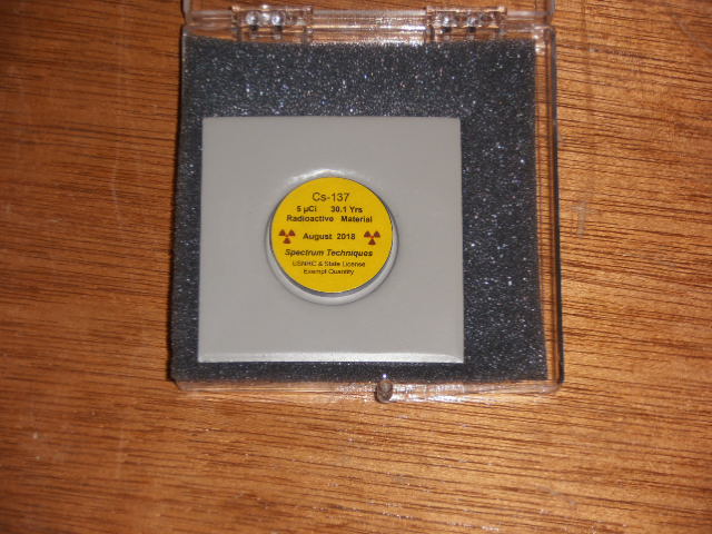
Got my 5 uCi source today. It did not come from Michigan, but from Tennessee. A company I've gotten quotes from before. Spectrum Techniques is in Oak Ridge, Tenn.
It came in an 8"x8"x8" box with label saying it contained radioactive material excepted for shipment.
Inside was the flat plastic case with foam liner and two flat lead plates 1/8" thick with little pie plate punches to hold two disks.
Image Insert:
74287 bytes
The disk, like GQ's, only dated August 2018.
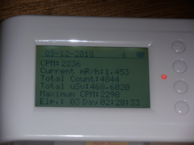
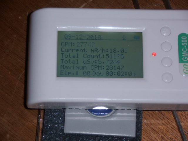
I thought it would be interesting to see just how much radiation made it through the lead. So put the 500+ with M4011 centered on the disk and recorded counts.
Image Insert:
77507 bytes
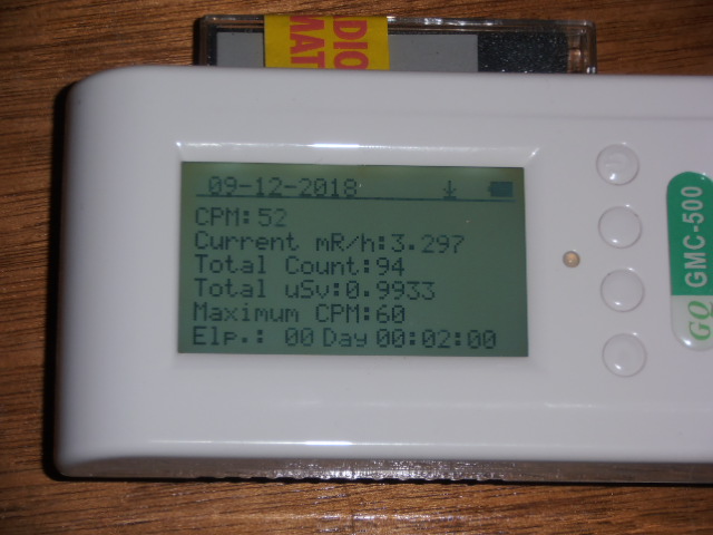
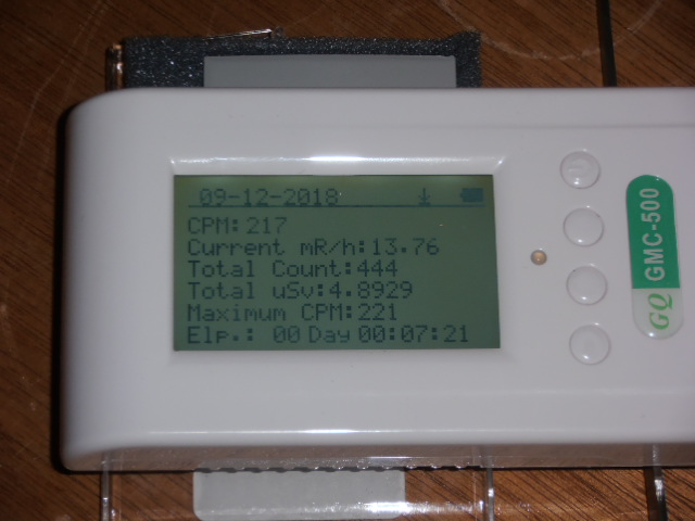
Then switched to SI3BG and got this
Image Insert:
78017 bytes
Didn't have time to get voltage data or to remove from case so ran a couple of quick tests with the 500+ laying on the disk first with the M4011
Image Insert:
81049 bytes
and then the SI3BG
Image Insert:
78987 bytes
And for fun I put the CD-V 700's wand into play with shield closed
Image Insert:
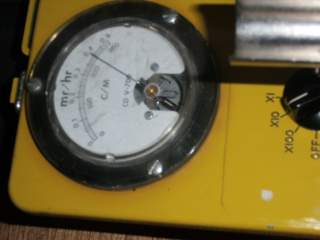
81769 bytes
and open
Image Insert:
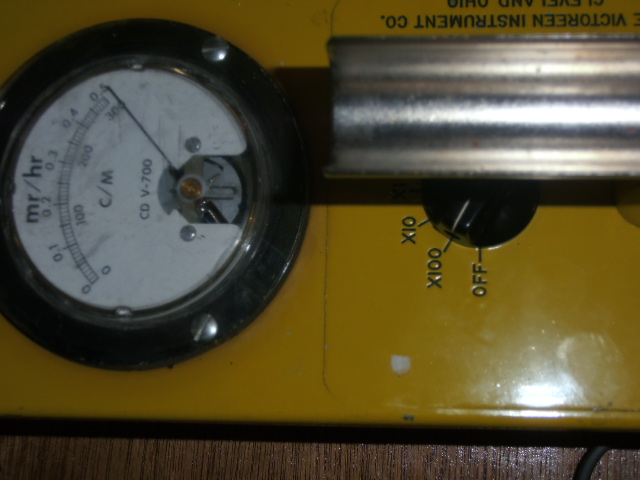
82179 bytes
That pegged the meter at 100X so more than 30,000 counts.
Lots more to do, but wanted to get some quick numbers to begin to play with when I have more time. |
| Stargazer 40 |
Posted - 09/12/2018 : 04:29:20
quote:
Originally posted by ikerrg
That answer looks a bit pejorative. Being a non-native english speaker does not mean that you don't understand the difference between 20% and (+/-)20%! They should have answered that "an incompetent person" had updated their web pages.
 |
| ikerrg |
Posted - 09/12/2018 : 02:39:19
That answer looks a bit pejorative. Being a non-native english speaker does not mean that you don't understand the difference between 20% and (+/-)20%! They should have answered that "an incompetent person" had updated their web pages. |
| ullix |
Posted - 09/11/2018 : 23:46:29
I emailed them already and they excused them saying that "a non-english person" had updated their web pages. Aha.
So now the text is changed and it says "Contains (+/-) 20% of the stated activity". Quite an uncertainty, and thus barely usable for calibration. But a comparably cheap source. |
| Stargazer 40 |
Posted - 09/11/2018 : 14:47:43
I have enquired of their sales staff just exactly what does that 20% number mean with regard to activity. Should hear back tomorrow, Wed, 12th. |
| ullix |
Posted - 09/11/2018 : 04:23:18
Blimey:
Read this website carefully: https://www.imagesco.com/geiger/radioactive-sources.html
Under the heading 'License free' near the top:
These are safe, uncalibrated solid sealed sources.
...
Contains 20% of the stated activity
You order 10�Ci, and we will ship you 2�Ci??????? Now, that is chutzpah!
|
| ullix |
Posted - 09/10/2018 : 23:54:44
quote:
Regarding your question, I think the sources are measured sans packaging. So sitting on the table in front of you the disk is emitting at 10 uCi whether German or US.
Yes, but with a US source you get twice the counts as with a German source. I'll report this separately, because I think it is quite important!
|
| Stargazer 40 |
Posted - 09/10/2018 : 04:57:41
Thx ullix! Very complete analysis as usual. I think the C60 is the logical choice even though only a 1 uCi activity level. I see US packaging requiring lead shielding for betas for 10 uCi and greater. I ordered one of the two disk lead shield flat cases with my 5 uCi source. If I get more I will get the cylindrical pig that is a lot thicker and holds eight disks, but not thick enough to cut gamma emission in half.
Regarding your question, I think the sources are measured sans packaging. So sitting on the table in front of you the disk is emitting at 10 uCi whether German or US. |
| ullix |
Posted - 09/10/2018 : 01:13:03
The perfect gamma source? An X-ray machine. Better yet, an accelerator of some kind.
Given that us normal mortals won't have access to anything like that, we have to settle for the imperfect stuff. For the US this list might show what is available: https://www.imagesco.com/geiger/radioactive-sources.html I find this list quite helpful
Exclude the alpha emitter.
Exclude those listed as beta emitter. While they may emit gamma also, this can be assumed to be the lesser activity.
Exclude everything which has gamma below the specified (whatever the value of those dubious spec sheets is) lower detection limit of the M4011, which is 100keV. This excludes Cd109, and I would add Co57, being marginally above 100keV.
Ba133 is supposedly gamma only, yet here h**p://www.spectrumtechniques.com/products/sources/ba-133/ they claim betas from B133. (seems strange, though, as gamma is from electron capture). Nevertheless, one should make the assumption that all those sources have both beta and gamma, and we use shielding to select for gamma only.
The good news is that for these kind of sources you have a rather clear situation, not as confusing as all the decay chains from Uranium and friends.
And pick the highest activity available (or you can afford), given that the betas will be excluded anyway and thus reduce activity available for experiments. Setting the min limit at 10�Ci, this leaves:
Ba133: low energy (~300keV)
Cs137: medium energy (660keV)
Mn54: medium energy (800keV)
Na22: medium and high energy (511, 1300 keV)
Alternatives but only available at 1�Ci:
Co60: high energy (~1300keV)
Zn65: medium and high energy ( 511, 1100keV - 0.6a half live)
the 511keV line is from positron annihilation and generally dominates the spectrum.
To cover the whole energy range you end up with the classic Cs137 plus Co60, complemented with Ba133.
One interesting question: how is the activity determined? Let's take Cs137, which emits 1 beta, followed by 1 gamma, but from the daughter nuclei (not 100%, but close). Since it is declared Cs137, I would assume that only the betas are counted in the �Ci. Since the German (EU) packaging absorbs the betas, while the US packaging allows them through, does a 10�Ci US source have twice the activity as seen by a Geiger counter than a German 10�Ci source? I found no specs on this question. Anybody knows?
|
| Stargazer 40 |
Posted - 09/09/2018 : 10:43:21
Well, It's 'only' $82 USD and if ordered with a second different source shipping may not be too bad. So if you're trying meters and seeing how they work it probably is worth it. Get it done in a month or so and you're in good shape. |
| ikerrg |
Posted - 09/09/2018 : 10:19:57
Cobalt 60 looks very good (https://en.wikipedia.org/wiki/Cobalt-60), as most of the betas are very low energy and very easy to shield, and the gammas are very high energy (almost as high as Potassium 40). However, the half life is only about 5 years, so the investment in a source does not last very long. |
| Stargazer 40 |
Posted - 09/09/2018 : 10:15:16
quote:
Originally posted by ikerrg
I have found a website where you can purchase gamma only sources, again only in the US: h**p://unitednuclear.com/index.php?main_page=product_info&products_id=819
Yes, this is the company that makes the sources. All those available whether gamma, beta or alpha are also available at Images IS where I ordered mine from. There is a cost difference and Images IS was actually cheaper per source disk. However they doubled the shipping cost after I checked out and notified me of the difference that had to be paid. Also the United Nuclear site says it takes 7-9 days to make the disks and I didn't get that information from Images SI when I ordered, only that it might take three days to process. So I have an email into them to see when this disk might finally ship. So we not only can order them, but have multiple sites to do some from so actually some competition out there controlling prices.
ullix, what is the best pure gamma source if there is such a thing. I thought it might be Cobalt 57, but still some betas and those gammas are lower energy I think. |
| ikerrg |
Posted - 09/09/2018 : 08:05:57
I don't think you can obtain the percentage between beta and gamma in the source by using the GM tubes because the sensitivities of the tubes to both radiation types are different and unknown. But you can obtain the ratio between the sensitivities of the M4011 and SI-3BG tubes in the same gamma radiation by using the beta blocking metal sheets. I suppose that the 32 keV gammas are also going to be shielded by the metal sheets, so you will be able to measure only the 661.6 keV gammas.
I have found a website where you can purchase gamma only sources, again only in the US: h**p://unitednuclear.com/index.php?main_page=product_info&products_id=819
|
| Stargazer 40 |
Posted - 09/09/2018 : 04:27:12
ullix, Thanks for sharing that website. Automess has been making dosemeters since 1970 I think and they are available here in US. They have some features that I think allow them to be considered professional meters, and that GQ should consider if they want to get into that market (I for one think they are not all that far away). The cases are made out of aluminum for added durability. They allow for a variety of probes to simply be plugged in (PTB approved, whatever standard that is). The 6150AD-t Teletector Probe is a dual tube external probe with the same idea behind it as the 500+ - low and high sensitivity tubes selectable. When it is plugged in, the tube in the 6150AD-6e is disconnected. External probes support cable lengths up to 100m (not sure if that is power drain on meter or self powered, but likely the latter). And similar to the Mazur series of detectors (~$600 USD) I've mentioned before, they are independently calibrated across the entire range. This 6150AD meter only comes with two ranges available - .01 uSv/h- 10 uSv/h and .1 uSv/h-1 Sv/h. Not indicated, but perhaps the external probe contains both tubes in one package.
I think for a highly portable personal dosemeter with built in tube, the Mazar 9000 is likely the closest US made meter fitting that purpose. If GQ wants to compete there, they can do so with the 500/600 series, simply by making a few changes to the hardware and having the devices independently calibrated. For the 500+, add the switch to turn off the low sensitivity tube; for 500/600 series meters, have them calibrated and provide independent calibration report for the design. Consider adding an aluminum case for durability. The 600+ already uses the gold standard LND 7317 pancake tube just like the Mazur 9000. The 600 uses the SBT-11 pancake, so perhaps not the choice of professionals for a personal meter. Mazur 7000 and 8000 meters use LND 713 and 712 tubes respectively. They are less sensitive, but the top of calibration measurement range is still only 5,000 uSv/h. I very much like the idea of the 600+ with its 7317 pancake tube in the case with an external wand with LND 712 end window tube for high and low sensitivity alpha, beta, gamma and xray measures. Put it all together in an aluminum case and add independent calibration and sounds like perfect meter for what we've been talking around here. Also, with the 712 lower sensitivity tube added to the 600+ GQ wouldn't have to boost the PS capability; only switch to 712 tube and carry on.
I also think the 6150AD meter is shielded for betas as it is described as a gamma/xray dosimeter only.
The source I am getting is pretty much exactly the same as ZLM's. Although marketed by various companies, they are manufactured and shipped by a company called Nucleus. One inch plastic disks with beta/gamma sources molded inside for safety. If alpha sources are added they are windowed somehow. Energies emitted by this source are:
Primary Radiation Type(s)
Gamma (#947;) & Beta (#946;)
Energies KeV
#947;: 32, 661.6
#946;: 511.6, 1173.2
I do plan on doing the beta blocking experiment to see what percentage is gamma versus betas. |
| ullix |
Posted - 09/09/2018 : 02:00:13
The situation in the EU is significantly different.
First you need to certified to being able to handle such radioactive substances. Then you need permission for the shipment. And then you need to shell out some 700� to purchase a 10�Ci Cs137 source (google for "Pr�fstrahler 6706").
And perhaps you want to buy a Geiger counter as used by the HazMat teams for 1500� ( https://www.gfd-katalog.com/schmitt_feuerwehrtechnik/dosisleistungs-messgeraete/14673 )
You can see in this brochure what a certified standard entails. Though in German, the pictures are telling. This is explicitly specified as a "gamma source". Given the mechanical design, I do believe that indeed no betas can be detected. Which of course will reduce the max counts you can get.
@Stargazer: if the source you get looks more like the one we could see in ZLMs video, I suggest to check with beta absorbers what type of radiation you see!
Where did the link to the brochure go? here again: https://www.automess.de/Download/Prospekt_6706_D.pdf
|
| Stargazer 40 |
Posted - 09/08/2018 : 18:57:56
I think for educational items like this they are perfectly legal here without administrative burden on my end, but there is a limit on activity and what you can send in the post or ship. You can buy a number of source types including Polonium and Cobalt. Limit is 10 uCi per source I believe, and they sell them in lead holders of up to eight. Pretty large price to pay for variety though, and I was looking for a similar comparison with GQ's.
Even these carry a degree of responsibility for proper storage and use. I don't plan on handling this directly, and will limit exposure with well planned experiments. My thorium mantles are kept isolated with the lanterns that also exhibit fairly good counts from their ashen counterparts mounted inside.
Cost for this is more than the meter but I do volunteer work with all hazard first responders and I don't want to be surprised because I don't know what I might be walking into. And it really is quite interesting to explore with both you and ullix, and of course the GQ guys. Reminds me of a 3rd semester nuclear physics lab course from many years ago. |
| ikerrg |
Posted - 09/08/2018 : 10:45:26
I am a bit jealous, Stargazer 40, that you can freely buy Cs-137 sources in the States! I cannot find them here in Europe, and I think ullix said somewhere that you need a license to own one, so the idea of buying it in the States and bringing it back would be against the law.
|
| Stargazer 40 |
Posted - 09/07/2018 : 14:58:23
Thanks EmfDef. It wasn't all that clear. I have ordered one of these 5 uCi sources and hopefully it will be dated middle of 2018. About a quarter of half life between the two so should see higher counts. In addition, I will test both tubes at the top or near the top of their plateau voltages (440V) to settle in my own mind how much I will gain from voltage tweaks. It will give us two points of control in addition to those provided by ZLM in videos. |
| EmfDev |
Posted - 09/07/2018 : 09:18:49
From video. it shows Apr 2011. |
| Stargazer 40 |
Posted - 09/07/2018 : 03:24:25
@ZLM, what is the date of your source? Looks like Apr 2010? |
| Stargazer 40 |
Posted - 09/05/2018 : 05:50:36
quote:
Originally posted by ullix
The tubes' specs all state a need for an anode resistor. This may have to do with the early power supplies potentially delivering more power than needed, and the resistors limited current flow so the tubes won't light up as light bulbs.
Well, it remains a requirement with modern power supplies as well as all of the LND detectors specify it as a necessary part of the system (10 Mohm).
Perhaps a better way to say it is as ZLM did above. We want the measure of the PS ability to support the tube's voltage requirements for plateau range. We don't need or want to average in dead time and at recovery point the BC approach better shows that given the samplings limitations/averaging of our meters. |
| Stargazer 40 |
Posted - 09/05/2018 : 04:47:51
Well, I really can't 'rest assured'. Might be common practice and I am simply ignorant. But you learned it somewhere and if I have googled it and can't find anything then it's not clear (also I don't read Russian). Also you don't comment on the whole dead time drop averaging in when the tube actually conducts, and even your oscilloscope doesn't show that for that moment the resistance goes to essentially zero. So the voltage is already going to zero across the tube for that moment and the only thing that matters is when it recovers, and the stability of the power supply to support it. We've seen that the recovery voltage drops in both situations (AC, BC), but the anode resistor supported measure doesn't drop as far. Both appear to need the same time to recover and they appear to recover to the same place (the recovery voltage drops the same amount at recovery with increased CPM) albeit the BC measure doesn't have dead time low voltage averaged as you comment on as it is averaged in by the meter, but your oscilloscope shows it does. ZLM makes the better argument for BC and you actually support it with your oscilloscope display. For me it's all about the CPM. You asked for data and ZLM provided it and it says the 500+ is much better than you have said it's limited to. You've had to continually adjust your limits upward. ZLM has acknowledge that the PS is a limiting factor. Yet we now also see that the SI3BG plays the high end part intended by GQ and does so quite nicely fitting the switchover part of my measurement charts pretty much as I made them within a week of getting the 500+. The 5 uCi source allowed that.
So I am left with my original expectations pretty much intact. The M4011 tube meets the 30,000 CPM crossover point in GQ's original firmware settings, and the SI3BG tube looks like it can handle (with PS tweak to top of plateau voltage) ~12,600 uSv/h (advertising to 42,500 uSv/h relates to counter limits and not what the device will actually measure in my opinion). It does need a hardware switch to run the tubes one at a time without the other interfering with the joint PS.
I appreciate all the effort and information presented here. I want to better understand my CD-V 717 ionization chamber meter (see if it actually works) and duplicate some of what's presented here for response of 500+. I've ordered a 5 uCi source disk ($110 USD) and with the 500+ giving 282 uSv/h (43442 CPM * .0065), we're looking at 30 mR/h and 8.5 times more activity than the gas mantles (43,442 CPM vs 5,100 CPM). On the 717's 0-5 R/h display, that's three chart division movement at the .1X setting. Ought to at least see movement of the needle where I couldn't clearly see anything with the gas mantles. |
| ullix |
Posted - 09/05/2018 : 00:59:45
I leave it to you to google for the specs. The tubes' specs all state a need for an anode resistor. This may have to do with the early power supplies potentially delivering more power than needed, and the resistors limited current flow so the tubes won't light up as light bulbs.
The capacitive issue is relevant when there are any long leads from HV to tube. Then you mount the resistor immediately at the anode. For the GMC counters this concern is not relevant, as you can't get any closer to the anode as you already are.
Rest assured that an anode voltage is measured at the anode, not somewhere else in the circuit. (Even if it does not matter without any current flow.)
|
| Stargazer 40 |
Posted - 09/04/2018 : 02:53:16
quote:
Originally posted by ullix
Sorry, but no.
The tube cares only about its voltage, more precisely the voltage difference between its anode and its cathode, and not about anything else in the circuit!
When you measure at point B you get a voltage higher than what the tube sees. Relevant is what the tube sees.
ullix, I understand what you're saying, but I asked about the voltage that is used in the specification sheet for the tube. An anode resistor is recommended in the spec. What documentation or reference can you provide that the voltages for the tube in the specs are not measured without that anode resistor in series? Can you provide a spec sheet that explains the voltage measured that specifically says anode to cathode voltage and not the system voltage with anode resistor? I have't been able to find one but discussion concerning measurement in other places seems to say you want to have a resister in series to eliminate stray capacitances.
As well, with each discharge the anode to cathode voltage of the tube goes way below the working range (and the starting max) voltages. So recovery is necessary before the tube can discharge again. The power supply if not damaged will recover to same level whether anode resister is in series for measure or not. So we are really only interested in recovery voltage for the next discharge. If we're pulling the PS down with many counts, you certainly will see that with the anode resistor in series for the measurement so the voltage should be valid. |
| Stargazer 40 |
Posted - 09/03/2018 : 12:34:07
Yes, for 450 CPM you dropped 2 volts across the tube and anode resistor (BC measurement). The working range of the tube is 380V to 460V. So you have a plateau width of 80V. For roughly 500 CPM per two volt drop you have 40*500 or 20,000 CPM the 500+ PS should be able to support with PS cranked up to 460V before making a measure (and of course slope is present to affect things). So 20,000 CPM at .6298 conversion factor is ~12,600 uSv/h. That's ten times the upper tested limit of Mazur 9000 (1250 uSv/h). Logic gotta be faulty somewhere there, but that sounds good to me.
Oh, as to effect on human, stay in that field for an hour and you get about 5,000 uSv/h shy of dose received for a medical PET scan (17,450 uSv). If we saw that reading we would certainly want to leave as soon as possible.
|
| ZLM |
Posted - 09/03/2018 : 10:52:36
The 449 CPM is relatively low count. Each count is about ~11uS width, the total time is about 0.00493 second. For one minute, this 449 CPM only consumed about 0.00493/60 = ~0.0082% of total HV power. That almost can be ignored for power consumption in one minute. This is why the HV voltage drop is not noticeable.
In first testing LND7317, the CPM = 201000, total time for this count is ~22110000 uS = 22110 ms = 22.11s. That is about ~36.9% of a minute. So, the total voltage should drop about 36.9% of the preset tube voltage of 670. Which is about ~247V drop. This is very close to our actual measured 242V drop.
If the HV PS is not a problem, with the pulse with 11uS for each count, and 4uS recovery time, we can calculate the maximum CPM we can get is about 4,000,000 CPM.
So, we need a stronger HV power supply for LND7317 to get 4M CPM. With 3M ohm resistor, we need a 670/3Mohm = ~223uA, 670V power supply. |
| Stargazer 40 |
Posted - 09/03/2018 : 09:34:46
But clearly ullix, ZLM achieved 449 CPM with SI3BG and voltage was still fine. He achieved 43443 CPM with M4011 and voltage was still fine. The only measure that was critical was the 7317 detector that was at its max start voltage of 425v. Not likely to get more out of that. Certainly the voltage is dropping with increased counts, but not as much with B-C as you point out. You say in Reply #17 that the 500+ PS won't support above 11,200 CPM for the M4011 and then in Reply #31 that it can't support 60,000 CPM, but we're getting close at 43442 CPM and the voltage hasn't been adjusted to 440v at the top of the plateau (still at 383v). So with that in place we might do much better than 60,000 CPM (you now mention 65,000CPM is likely in Reply #86). And I also think we need to explore the top end of the SI3BG capability and if the 500+ keeps counting well below the max start voltage with A-C measure then the specs have to be describing a B-C measure. |
| ullix |
Posted - 09/03/2018 : 09:06:20
Sorry, but no.
The tube cares only about its voltage, more precisely the voltage difference between its anode and its cathode, and not about anything else in the circuit!
A plain resistor in series with the tube will see the same fluctuating current that the tube sees. But since its resistance in less than that of a tube between conducting and not conducting, the signal at the resistor will change accordingly less during a pulse.
Easy enough to measure, see picture. All traces DC coupled via 1GOhm
Left shows tube anode_vs_gnd voltage (blue) and voltage between your point B and GND (yellow).
You see the pulse in both traces.
What you also see is that the voltage at CPM5000 (left) is lower than at CPM=20 (right).
Image Insert:
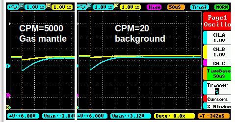
12997 bytes
When you measure at point B you get a voltage higher than what the tube sees. Relevant is what the tube sees.
Use an oscilloscope if you want to avoid averaging over the pulse period with a DVM.
|
| Stargazer 40 |
Posted - 09/03/2018 : 08:15:06
Thanks, and the tube specs specify the anode resistor size/range so it fits that it is expected to be a part of the measurement. You might look at your sticky link on measuring the voltage of the tube where someone asks about if he should measure AC (at the ends of the tube). I think my impression from that thread is that you do use the ends of the tube (AC) and maybe you should edit response with diagram above to clearly indicate including anode as in BC. Thanks.
|
| ZLM |
Posted - 09/03/2018 : 07:14:09
The tube only works within working voltage range(DC 330-380V here). The resistor limited the tube discharge current on each pulse, during the discharge time, the voltage on tube may drop to between 0-330V. That is tube dead time voltage. It needs time to recover back to tube voltage (330-380V here) in order to discharge again. We do not want to check the tube dead time voltage. We need to know how high the tube voltage the PS can provide during the high CPM. |
| Stargazer 40 |
Posted - 09/03/2018 : 06:49:25
But what measure (AB or EC) is used for the tube spec? If it is AC, then the tube will fail due to counts. It looks like many more counts are viable if BC is correct and you certainly see a LOT more counts than ullix predicts from his voltage drops. Ullix, are you including the anode resistor in your measurements? |
| ZLM |
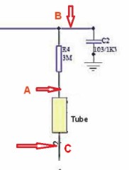
Posted - 09/03/2018 : 06:35:38
The R4 is for limiting the HV current to tube when counting. I think that controls quality of the counting pulse from tube too.
I used B-C points to check the voltage.
This may explain why my voltage has some differences.
See:
17995 bytes |
| Stargazer 40 |
Posted - 09/03/2018 : 06:25:14
So you are saying the anode resistor (3M, R4 in diagram). Needs to be incorporated for high CPM. Is that stated in some document that describes how working ranges in tubes are determined? I mean are the numbers in detector specs for working range voltages all measured with the anode resistor included? I have not done that, but would like some published documentation (reference) that supports what you have said. |
| ZLM |
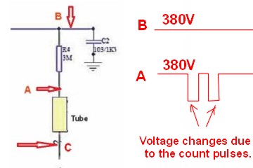
Posted - 09/03/2018 : 06:00:44
For the voltage measurement, I want to make clear on how to get correct tube voltage.
See:
7012 bytes
There are two ways can be used to check the tube voltage:
1. A and C.
2. B and C.
When the CPM is very low, like background reading <50 for example, they are no difference. They have same voltage.
However, when the CPM goes high, the A-C voltage no longer be a stable DC voltage due to the count pulses.
So, when measuring the tube voltage while a high CPM reading, the correct measurement points should be between B and C. Otherwise the tube voltage will be incorrectly measured.
|
| Stargazer 40 |
Posted - 09/03/2018 : 05:01:07
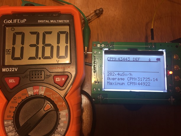
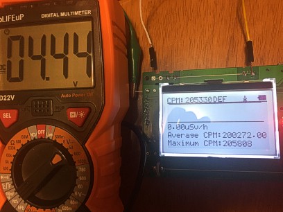
Sorry ullix, but I don't think you correctly understand the Average CPM number. From the manual, the Average CPM is the average reading of the counts per minute SINCE POWER ON. We have no idea what amount of time the meter has been on recording background that has been averaged in unless we look at elapsed time (but that is not shown in this graphic display). You are correct that the Max CPM is not what we want as that rate is likely calculated from extrapolation of CPS. But the number that is important (after sleeping on this and rereading the manual) is the CPM in the upper left corner. That CPM is total counts for the last minute. When the source is applied it starts to rise and when the source is removed it starts to drop. ZLM was careful to only record for one minute with the application of the source and then remove it. So for the first video from the upper left corner CPM number we still get ~17,500 for the M4011 and for the 7317 it is ~200,000. On the second video for the SI3BG tube the number stabilizes at +440 CPM. You can watch the CPS graph and note the up and down changes, yet the number of counts increases in the upper left corner till it stabilizes. There is more variability in the number as the tube is so much less sensitive.
For the last two shown pictures the CPM we want is again upper left and with better location of source to tube the number is 43443CPM for M4011 and 205330CPM for 7317. The source was already better placed in the SI3BG experiment. So with this 5uCi source the CPM numbers we want are
7317 - 205330
M4011 - 43443
SI3BG - 449
The 7317 is 4.73 times more sensitive than the M4011 and the conversion should be .0065/4.73 or .00137
The M4011 is 96.75 times more sensitive than the SI3BG and the conversion should be .0065*96.75 or .6289
Of course for this source only.
With voltages shown we are certainly at the limit for this counter (in my opinion) regarding the 7317 tube. And very close to the limit with the M4011 tube (Still, I think your 65,000 number is good with PS voltage turned up to 440v and that is 422uSv/hr). I think the SI3BG tube has a long way to go as long as M4011 is removed from device and PS voltage is inreased to top of plateau for the tube. We really do want a hardware switch to turn off M4011 when in incident level fields.
The Radex meter states max range tops out 999uSv/h (SBM20 tube). Given what we've seen, with no test report available, I don't believe it. Number of convenience and display limited at three digits. For the $600USD Mazur meter there is a test report that says it will read up to 1250uSv/hr within 10% so I do believe that. More than three times the cost and just the 7317 tube alone accounting for much of that cost increase. But more sensitive low end for sure and PS to support more than three times the counts we're seeing here in ZLM's experiment. But for more than a third less cost we have the added SI3BG tube with the 500+ to take over when M4011 craps out on voltage drop, and I think we need to explore the upper end of that tube's range further with this PS raised to top of plateau voltage and this higher energy source (higher than gas mantles). Also, ZLM got ~450 CPM from the the 500+ and SI3BG. Your RadMon+ voltage drop with counts shown in Reply #31 for the SI3BG shows that highly unlikely. So the RadMon+'s PS has to be significantly different to counts than the 500+. ZLM recorded that ~450 CPM number with still adequate voltage (and from starting at 380v).
|
| ullix |
Posted - 09/03/2018 : 02:22:13
Thanks, ZLM. What I see is basically a full confirmation of what I had predicted. I got confused by your initial post which I misread as CPM=120 000, instead of the actually posted CPM=12 000.
So now in the videos we saw a 14V drop of the original 383V for a max CPM of 17000, which means a 55V drop when the counter reaches 65000CPM. That covers largely the whole plateau, i.e. a GMC counter with a M4011 will stop working at something around CPM=65000!
Why are the MAX values always that much higher than the average? relevant in this discussion is the average, not the max!
Note that Cs137 is actually a pure beta emitter! It is the daughter nuclide Ba137 which decays by gamma emission. Hence you get a 100:95 ratio of beta to gamma. Some Cs sources are sealed in sufficiently thick steel to let only gammas pass, but your sample seems to be too thin for any beta shielding. And the imprint on the source clearly says "beta/gamma". Thus you have a mixed beta/gamma source, just like you have with K40 and the gas mantles.
So, one CANNOT draw any conclusions re the sensitivity of the M4011 to the SI3BG to gamma!
If you wanted to determine this, you could put a beta absorber between source and tube, and repeat the experiment. As the max beta energy is rather low (~half of K40) a shield from 2mm steel or copper, or 3mm alu, or 100 sheets of copy paper should suffice.
The LND7317 is an interesting tube. The reason for it showing much higher count rests clearly on its much larger size and the Mica window, which lets pass a lot more of the betas. (Try here also with the beta aborber described above). Though 5�Ci or 185000Bq is CPM=5.6million (one side of the source is caught only). With a max of CPM=200000 the efficiency even of this tube is <4% only!
For the LND7317 experiment, the voltage drop from 670V to 428V is 242V for 201 000CPM. A 14V drop would be achieved with 201000/242*14 => CPM=11600. This suggests that the LNB7317 is drawing even a little bit more current than the M4011, but you could manage because you tuned the starting voltage to a much higher level.
This means due to the declining voltage, you will count relatively fewer counts at high count rates than at low count rates; you slide down the plateau.
Actually, looking at the tube specifications at the LND site ( https://www.lndinc.com/products/geiger-mueller-tubes/7317/ ) you were working really borderline with these voltages:
OPERATING VOLTAGE RANGE (VOLTS)	    475-675
MAXIMUM STARTING VOLTAGE (VOLTS)    425
The tube will cease to count at around 425V, i.e. around CPM=200k - you were lucky and just caught the maximum!
The conclusion is unchanged:
The counter and tubes perform as expected from my earlier experiments.
The limiting factor in this counter and all other GMC counters is the high voltage generator.
|
| ikerrg |
Posted - 09/03/2018 : 00:36:41
First of all, many thanks for the experiments, ZLM. That is really good stuff. Now we are talking the same language and we are watching real data!
Before your reply #84, I was just going to say that the location of the cs-137 source was not the same for the M4011 and for the SI3BG, and hence the reduced ratio in sensitivities between both tubes. Now, the ratio 45000/450 = 100 is more similar to what ullix and I found in the different experiments for gamma radiation. And by the way, yes, the tubes behave very differently to beta and to gamma, and therefore the ratios are also different (around 475 for beta). And also yes, the high radiation tubes like the SI-3BG seem to be only specified for gamma in the original specs, which makes a lot of sense for an incident.
I suppose that ullix will be able to comment more on the voltage drop experiments, as he has all the data and the setup. It looks like the voltage does not drop under 360 V for the M4011 tube when reading 45000 CPM, which is good news, but it does not totally align to ullix�s predictions. I suppose that the starting voltage for that experiment is the same as before, i.e. 383 V, am I right? On the other hand, could you comment on the specs of the high voltage probe? It is possible that its impedance is higher than 1Gohm...
I miss in the experiments what would happen in the reading of tube 2 when tube 1 is measuring 45000 CPM. To do that test you would need another identical cs-137 source to put near the SI-3BG tube, and you can use the �Large font� mode to see the CPM of both tubes. That experiment would be definitive to demonstrate that the GMC-500+ can read moderately high doses with both tubes at once.
In any case, it looks that the high voltage circuit can be tuned slightly over 383 V for the stock GMC-500+, just to be sure that both tubes are within their voltage limits at any count rate. I wonder if the voltage drop for 45kCPM in the M4011 tube would be the same if the starting voltage was higher (higher voltage=higher power for same current).
Finally, I would remove from the firmware the addition of the CPM values of both tubes, because that makes no sense as ullix and I have said many times! In your pictures/videos, we cannot always know if the CPM shown is including both tube readings or only the tube being tested.
|
| ZLM |
Posted - 09/02/2018 : 23:31:44
Adjusted source position and tested again and got newer value:
Placed the testing source contacted the M4011 tube, the reading is 44922.
Placed the testing source contacted the LND7317 tube, the reading is 205808.
M4011:
72763 bytes
LND7317:
37827 bytes |
| ZLM |
Posted - 09/02/2018 : 17:23:30
First, the high dose tube has higher deviation on low dose reading. It may only work well on high does reading.
Second, Most of high dose tubes are designed to be more sensitive to Gamma ray. If I am not wrong, the gas mantles mainly for beta and alpha, Gamma ray in a small portion. The cs-137 has much more Gamma ray portion. That may be the reason and can be confirmed by checking the gas mantles radioactive decay chain if needed. |
| Stargazer 40 |
Posted - 09/02/2018 : 16:37:27
Thank you so much! So 17,500 CPM for M4011 and 449 CPM for SI3BG means 39 times less sensitive. Quite a difference from ullix's sensitivity comparisons up in reply #31 for this Ce137 source compared to the gas mantles. So 39*.0065=.2528 conversion factor. I got .458 from the gas mantles experiment so maybe difference is the type of radiation? |
| ZLM |
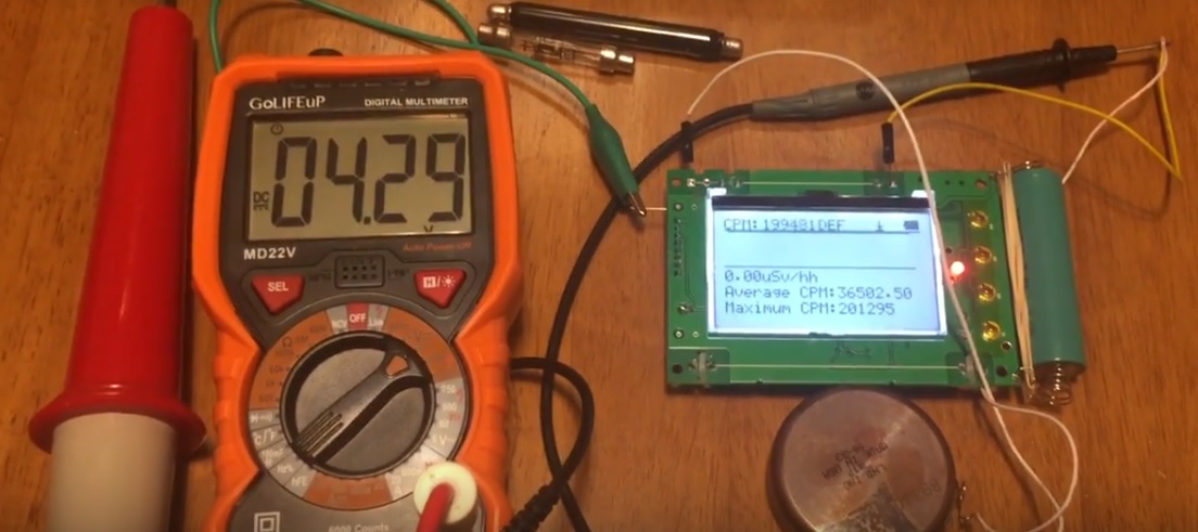
Posted - 09/02/2018 : 15:17:26
Here you go:
https://youtu.be/cfr3k2Blabg
For this particular tube, it showed a 449CPM ~87uSv/h on a 5uCi Cs-137 source.
Setup:
157303 bytes |
| Stargazer 40 |
Posted - 09/02/2018 : 12:08:40
Thank you ZLM for showing us the video. With 17,500 CPM for the M4011 tube we are looking at ~115uSv/h. On ullix's graph in Reply 17 above he got a projection of 11,200 counts at 360v, so his curve is sharper drop in voltage than your data point shows. This would change the upper limit of measurement with the voltage set at 440v, the upper end of the plateau.
The 7317 shows itself to be more than six times more sensitive than the M4011. Six times is from what you show on website for 5uCi source. Yet here it is 11.5 times more sensitive. To achieve the 201,000 counts there is a 250v drop in PS voltage. 429 volts is just slightly above the starting voltage for the 7317, and it is out of the plateau range of 475-675 volts. Given any higher counts would likely drop the voltage below the starting voltage of 425v, wouldn't you agree that the limits of the 500+ with a 7317 probe would be about 125uSv/h. With the M4011, I think we really have a chance for those 53,000 CPM and around 380uSv/hr.
I very much like the idea of an add-on kit for the 500+ whereby we could use the 7317 tube with the 500+ for more sensitive measurements of food and the like.
Could you repeat this experiment with the M4011 tube removed and only the SI3BG tube collecting data so we could see the same experiment with what level of counts the 5uCi source gives us for that tube? Maybe we can get a better number for conversion factor. Thank you. |
| ZLM |
Posted - 09/02/2018 : 10:02:09
I got time to repeat my LND7317 tube testing on GMC-500+. The results are batter than I expected.
See video:
https://youtu.be/O6d3rNVgVD8
Setup:
125128 bytes |
| Stargazer 40 |
Posted - 09/01/2018 : 07:04:24
Corrected conversion factor above. I can see that the counts for gas mantles are up 10% over what I was getting max before. So the slope certainly is real. Didn't actually change calibration. A 10% add to reading is easy to do in head.
Spoke to the guy at Mazur yesterday about their PS. He said it was the most critical design problem they dealt with. They send representative samples of their meters to AKM Calibrations in North Carolina and show report on website. Range of meter is listed as .01uSv/h to 1250uSv/h. Calibration report shows error less than 10% for that range. GQ ought to consider a similar approach for whatever range they think is truly viable for their meters as to actual use and not for counter's ability to count to only. |
| ullix |
Posted - 09/01/2018 : 01:08:53
I guess you have one 0 too many in your new calibration factor?
But it is pretty futile anyway, to "correct" this factor. Remember that it had been 0.005 when the 300 came to market, and with the very same tube it is now 0.0065. Which one is correct? If any.
There has never been a description on how this number was obtained. My guess, as I describe in my GeigerLog manual, probably just the average of two values as determined for the SBM20 tube.
There exist no data to justify the 0.0065!
And while the SBM20 gives individual values for different radiation sources, and even your old clunker of a Geiger counter is careful to qualify its calibration for "radium-equivalent radiation".
The 0.0065 may be right for something, but will be wrong for almost everything. Your correction may have made it worse. Nobody knows.
|
| Stargazer 40 |
Posted - 08/31/2018 : 16:28:55
Today I adjusted the voltage of the PS to the top end of the plateau voltage (or as close as I could get) of 440VDC from specs above. Actual reading was 446VDC on the 1Gohm setup. As well I believe I need to raise the conversion factor in the calibration section to .00715, up 10% from the reading it gives at the 407 VDC I started from due to slope change. Voltage adjustment was quite sensitive, but rather easy to do. I think this gives me the best chance to get the 53,000 CPM ullix computes above from the M4011 tube at 355VDC. I think that is around 40mR/h or 379uSv/h. It's also where I cross over to the SI3BG tube and at 40mR/h I think I should see somewhere on the order of 150CPM with the power to the M4011 tube turned off or the tube removed. This exposure rate for one hour gives a dose of about a tenth of annual background dose. |
| Stargazer 40 |
Posted - 08/29/2018 : 05:44:46
Measured the voltage of the 500+ this morning with and without the 1Gohm probe. 407VDC with probe and 146VDC without. This is just a tad higher than the midpoint of the working range/plateau. It seems to me that to get he maximum range possible within the plateau that the PS voltage should be set to 440VDC to maintain linearity (albeit with slope) in measurements.
The SI3BG has a similar working range but a little higher on the top end by 20VDC. Maybe a good compromise would be to change to 450VDC, but I doubt that the SI3BG would ever strain the PS unless in the midst of an incident and the M4011 would be removed anyway so will shoot for 440VDC in my raising of the PS voltage.
|
| ullix |
Posted - 08/29/2018 : 02:09:18
Wonderful, looking forward to it!
Yeah, Frankfurt vs Seattle - there are a few things here where we may have an advantage ;-)
|
| ZLM |
Posted - 08/29/2018 : 00:49:43
No problem, I will test it again once I go back from trip. I am in Frankfurt now. Nice weather here by the way.
I have cs-137. Once I got chance,I will upload a video. However, everybody can test it too.
The M4011 CPM is in the same range of your testing.
But the LND7317 tube CPM is much higher. That indicates the LND7317 consumes much less current than M4011. That is why it costs 10 times higher.
Different tubes have different gas filled. Those are affecting the resistance when it is conducting. |
| ullix |
Posted - 08/29/2018 : 00:24:17
@ZLM: With all due respect, but I don't believe these numbers! I've now heard too many of the 'dog ate homework' excuses from GQ, that I do want to see data. Prove them - that is all I am asking.
Though, if you did get numbers like 150000 - which I believe is not possible on a current 500+, also not with this pancake detector, as it will draw a similar current - why would you want to improve the HV generator, if you are already getting these high numbers? It seems to be not supporting your claim.
Since you do have a 5�Ci Cs-137 source, put it in front of a 500+, and record for a few hours, preferentially with GeigerLog, as it can handle both tubes, and post the recordings. I will analyze the data as I did with other user's data. Your chance to get a positive endorsement!
GeigerLog will be out as the new version 0.9.08 before the beginning of your day, so it will be waiting for you!
I can easily be convinced otherwise by just a few data! |
| ZLM |
Posted - 08/28/2018 : 23:01:46
Stargazer 40, thank you for sharing pictures. It is a good probe to measure the high voltage.
Just for you information. I ever tested GMC-500+ with a LND7317 tube only with tube voltage about ~500V.
I do not have high voltage probe, I use my 10M ohm DVM estimates.
With a 5uCi Cs-137 radioactive source, the GMC-500+ got about 150000~160000 CPM reading.
With M4011 ~380V, it was about ~12000CPM if I remembered correctly.
I believe with improved HV power supply circuit, the GMC-500+ can have a much better performance on CPM. |
| Stargazer 40 |
Posted - 08/28/2018 : 16:01:28
quote:
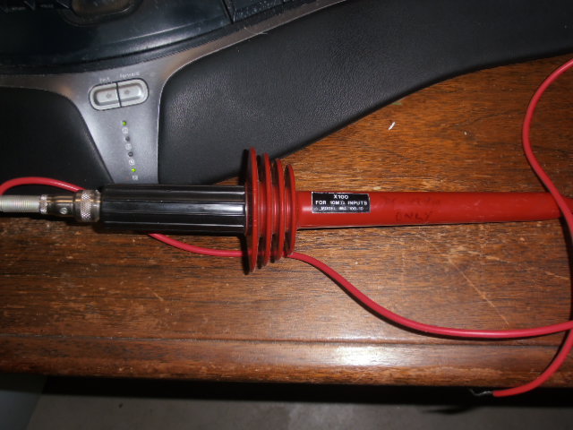
Originally posted by Stargazer 40
I will add more when I have more to add.
I bought this HV probe for use with an oscilloscope. It says X100 for 10Mohm input. Someone had written on it 10Mohm VTVM DC Only. Never gave it much thought till my latest offer for a 1Gohm resistor from China was not accepted. Dug this out and took apart and found a Beamen 990 Mohm 1% resistor. Now I can adjust the voltage on my 500+.
Image Insert:
75311 bytes
Image Insert:
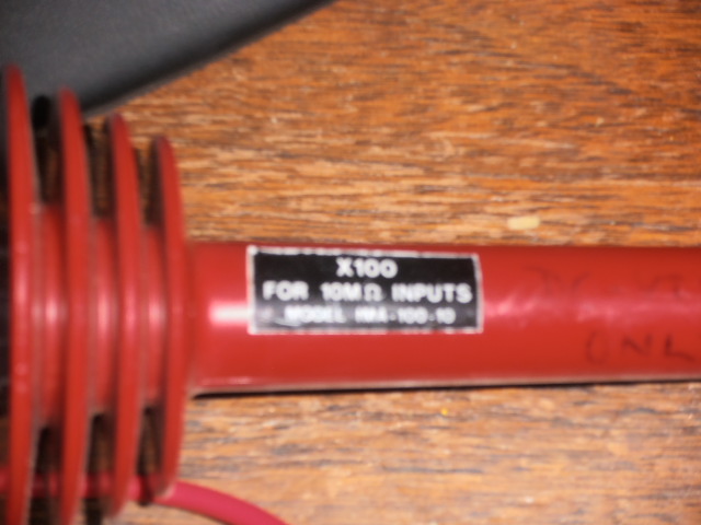
83319 bytes
Image Insert:
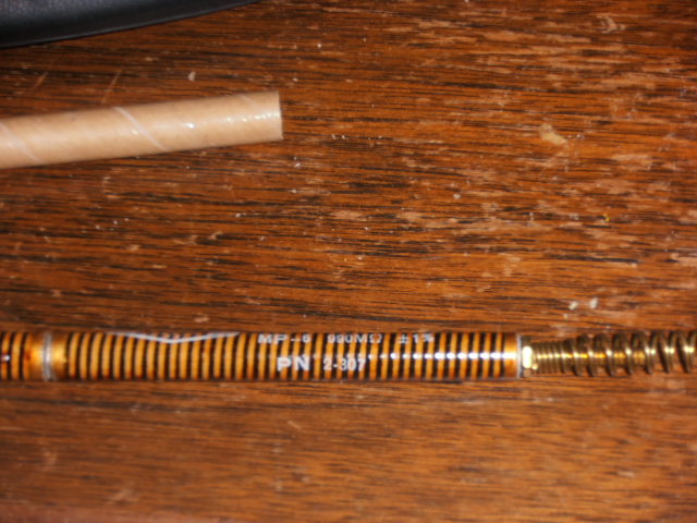
83215 bytes |
| Stargazer 40 |
Posted - 08/28/2018 : 09:28:43
I believe GQ is perfectly comfortable with their understanding of their specs. In the US we have a commercial products evaluation group known as Underwriters Laboratory. When we buy anything that plugs into the wall there normally is a label on the cord that says UL Approved. Doesn't mean the device will do anything we think it ought to; just means it won't likely short out when plugged in according to their testing (yes they do test things). GQ meters have been consistently ranked in the top ten of these types of dosimeters with high praise for features and build quality. I have often wondered how many of these rankings were more than label comparisons that anyone considering purchase with reasonable common sense would do. Ullix might consider a new service testing various meters for delivering what the label says or not. Of course there are likely far more stringent requirements for government measuring devices where these things take on a completely different level of seriousness.
In any event, I believe your attitude towards what to do next is a good course. GQ remains one of the most open companies I have dealt with and I may have gotten a little more info in talking to tech support instead of trying to glean thing from forum discussions, but then those conversations are not indelibly recorded on the internet. Thanks to both of you for continuing your study of these devices. I will add more when I have more to add.
|
| ikerrg |
Posted - 08/28/2018 : 08:40:39
I do not want a refund, partly because that would involve additional shipping costs that I do not want to pay for. What I want is to use this device as a test bench to play and to learn. Time permitting, I want to add the switch to the first tube, I want to switch the second tube by a SMB-10 (I am still waiting for it to arrive) and now that I know about the HV limits I want to talk to some colleagues at work that might be able to help me to improve that. I will document all these mods as I go through them and share them in this forum.
I would also like that GQ would give some advice to improve the hardware of the GMC-500+ devices, even if that involves admitting that they are flawed in their specs.
|
| Stargazer 40 |
Posted - 08/28/2018 : 07:59:24
As I said, you do have options that include requesting a refund. It was naive of us all to not understand that the ten fold increase in measurement range and movement to 32 bit processor from 16 bit processor were related. GQ did confirm that the published range increase was due to processor count ability when I contacted tech support. As well, the tubes do not stop counting either at the top or bottom of plateau voltage. They simply no longer are linear response. So GQ can certainly say that counts are being recorded throughout the voltage range provided by the device, but really we know the tube will fail either from the voltage being too high or stop counting when voltage falls to a point where there is no longer an avalanche effect. The power supply limitation really is the most important thing I believe has been determined here (and is the Radmon+'s critical limitation also).
I liked the idea of the ten fold increase. But I know better now. I like the idea of two tubes working together to characterize a broad range of response, but I know a lot more about the limitations of that now, and not only for this meter, but will question any manufacturer of similar capability with a lot more background as a result of yours and ullix's efforts here and you deserve our thanks for that.
|
| ikerrg |
Posted - 08/28/2018 : 07:37:21
You always refer to the reduced cost of this device compared to its competitors. Again, that is not a fair excuse. If you buy a Volkswagen Polo instead or a Ferrari F40, both are cars, both can be used to commute to work, but the former is not advertised to have the characteristics (speed, acceleration, etc.) of the latter and it cannot be used to win a championship in a race track, and nobody expects that. Therefore, when you buy a Volkswagen Polo, you know that you can only travel at 130 mph max. and therefore you are not cheated with a speed range of 0 to 200 mph! You pay with real money, and you receive the real specs that you paid for! That is the only complaint I can make to GQ, because the GMC-500+ is clearly a nice device to start learning about radiation measurements and to play with at a limited cost.
quote:
I think as stated previously we are looking at the published specs characterizing the capability of the new 32 bit processor and not the capability of the gm hardware.
That has not been confirmed by GQ as far as I know, and in any case it should be clearly stated in their specs and in the comparison document, to stop cheating anybody with the huge reading range of the GMC-500+.
quote:
That said, I, like the majority of users no doubt, am quite pleased with what I can do with the device as to background counts, and that there is utility in the event of an incident occurrence
We have already seen users in this forum not being able to use their GMC-500+ at high radiation levels (i.e. cancer therapy), and they were not involved in nuclear incidents! We have also seen that an Xray machine in an airport could be reaching those levels, and it seems that it cannot be accurately measured with the GMC-500+ unless you remove the first tube. Those are facts shown in this forum. Those users bought this device instead of the GMC-3XX because of its increased detection range.
quote:
I do not believe there will be an adequate hardware fix (or firmware for that matter) for this device anymore than we will be able to adequately make use of the second less sensitive tube without physically removing the M4011 tube from the current hardware configuration.
Well, GQ could explain themselves and say that the only way to use the second tube is by physically removing the first and they could propose a hardware switch (tested in their labs) to add in series to the first tube that does not disturbs the normal low radiation level readings.
quote:
I truly believe that you both have made your point ad nauseum regarding the true capabilities of this GM dosimeter.
I do not think that ullix is trying to be boring by testing and retesting the device. This is really useful information for GQ engineers (subcontractors?) and they should be answering these posts with useful data and information about their intentions and aims. Until now they are saying nothing about this problem! You have given more information only in the last post than what GQ have said since ullix started this thread!
quote:
I think we have been made aware of issues that likely affect all these inexpensive meters and not simply those manufactured by GQ.
Yes, but the big difference is that the other inexpensive meters are advertised with a correct reading range (like the GMC-3XX series). And in the case of the RadMon+ DIY open source project (=free), that limitation is even described in its design manual, so you can cope with it in the best way that your electronics knowledge allows you to!
|
| Stargazer 40 |
Posted - 08/28/2018 : 05:34:44
Thanks for all the work ullix! I take it you have made use of the pot to increase the voltage of the 500+ PS for your tests. I would ask how sensitive it was to small adjustments of the pot? Still waiting for my 1Gohm resistor.
I think as stated previously we are looking at the published specs characterizing the capability of the new 32 bit processor and not the capability of the gm hardware. If there was a tube that would be able to stay in the plateau voltage range while receiving millions of CPM, the new counting hardware could handle it. I do not believe there will be an adequate hardware fix (or firmware for that matter) for this device anymore than we will be able to adequately make use of the second less sensitive tube without physically removing the M4011 tube from the current hardware configuration. That said, I, like the majority of users no doubt, am quite pleased with what I can do with the device as to background counts, and that there is utility in the event of an incident occurrence. I truly believe that you both have made your point ad nauseum regarding the true capabilities of this GM dosimeter and have reached a point where you need to move on to replacement (possible refund in ikerrg's case) and seek a meter with capabilities that meet your obviously much greater count accuracy needs. That the Radmon+ can handle only a factor of two more counts than the 500+ shows me that very likely all these inexpensive meters have high voltage PS limitations that would make them less useful at true incident monitoring levels, which we don't care to be around evaluating anyway.
I have discussed the PS issue with tech support. I for one think that some form of regulated, constant voltage PS needs to be incorporated into a new meter along with the higher ranged counter that will hold voltage in the plateau range no matter what current is flowing, and that will cut supply voltage to most sensitive tube when counts exceed some number so that only least sensitive tube is powered. I think the cost of such a PS would greatly add to the cost of the meter, perhaps by many hundreds of percent. Not sure about the market for something like that, but perhaps development of such a device by GQ would take them to a new level of performance whereby the count capability of the processor is better matched by the hardware, much as the hardware and firmware handling of the second less sensitive tube (and indeed the selection of the tube itself) needs to be redesigned.
I very much appreciate this forum. I think we have been made aware of issues that likely affect all these inexpensive meters and not simply those manufactured by GQ. |
| ullix |
Posted - 08/27/2018 : 11:12:00
I guess the limit of the GMC-300 counters of 327.99�Sv/h, and a few lines later of 327.6 �Sv/h, has a much simpler explanation:
Initially the "calibration factor" for the M4011 tubes was defined as 0.005 �Sv/h/CPM. You find this mentioned in some old forum posts.
Multiply the max 16 bit number of 65535 with 0.005 and you get 327.675.
By whatever magic they ended with 327.99 remains another mystery. Neither this 0.005 nor the 0.0065 value is supported anywhere with data.
|
| ikerrg |
Posted - 08/27/2018 : 07:54:56
Thanks again for that extremely good analysis, ullix. All that confirms again the problem in the GQ counters and now we really need some official answers from GQ on how to proceed (if there is a possible hardware fix, etc.). It is clear that the only workaround is to accept that the GQ products with a M4011 tube are limited to around 50k CPM and, specifically for the GQ-500+, that the only way to use the second tube is by physically removing the M4011 (maybe with an externally accessible switch?). The GMC-500+ high radiation range is completely useless as it is sold!
To be clear, the problem of the HV network does not only apply to the GMC-500+, but probably also to other GQ single tubed devices, as ullix also demonstrated in the GMC-300E+. However, in the specs (http://www.gqelectronicsllc.com/support/GMC_Selection_Guide.htm ) the limit for the GMC-3XX is 328 uSv/h, i.e. 50k CPM, which is according to ullix�s limit. Is it possible that somebody designed the GMC-3XX with that limit in mind? Is it possible that the hardware limit was forgotten some time later when GQ decided to create new products with a 32 bit processor?
Please GQ, we need your answers and fixes!
|
| ullix |
Posted - 08/27/2018 : 01:53:04
quote:
You may just resolder all related components
So, the GMC-500+ as your own little Do-it-Yourself project, just like the RadMon+? Do you realize that all the 'related' components are SMD parts, and they are really, really tiny?
Maybe I should start the resoldering at the High-Voltage generator, because this is where the 500+ is really lacking. The RadMon+ show how easy it is to make it better.
I had tried to determine the max count rate supported by the GMC-500+ and came to a disturbing limit of marginally above CPM=10000, see Reply#17 of this thread. As I have no more powerful radioactive sources, I took a different approach.
Both tubes were removed and the M4011BLK holder connected to a resistor cascade. The anode voltage was measured via 1GOhm resistor, the current calculated from the known resistance.
Same setup used for the RadMon+.
This is the result:
Image Insert:
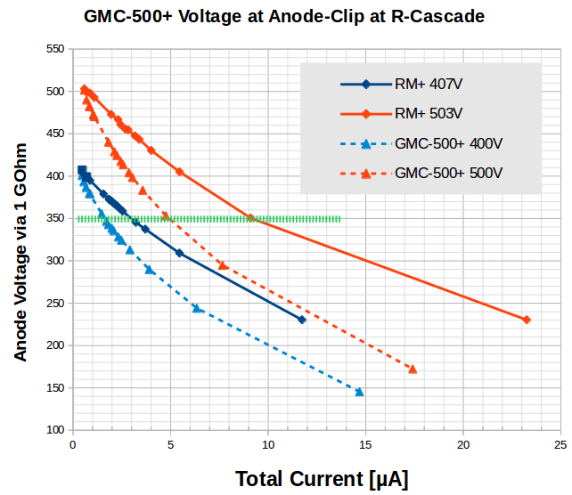
62247 bytes
The no-load anode voltage was set to either 400V or 500V. Overall all 4 curves are similar. With increasing current the voltage drops, as is to be expected.
Clear to see, the RadMon+ has almost twice the power of the GMC-500+!
350V is the bottom limit for the M4011 to still deliver counts, i.e. the left limit of the plateau, shown as a dotted green line. At this level the 500+ (red curve) delivers ~5�A, while the RadMon+ almost twice as much. Similar, at 400V, the 500+ is limited to ~1.5�A, the RadMon+ to ~3�A.
As the current through the tube is proportional to the count rate (below saturation), it becomes clear that both systems will have a maximum count rate they can support, because the voltage must stay above 350V. The question then becomes: what is this limit?
From the experiment at Reply#17 I got a preliminary value of 0.095�A/1000CPM. This allow to calculate the max count rate:
Device �Amax (400V) �Amax(500V) CPMmax[400V) CPMmax(500V)
GMC-500+ 1.5 5 16 000 53 000
RadMon+ 3 9.5 32 000 100 000
The 500V starting voltage is already well beyond the recommended upper plateau range of 400V (specs in #17). The consequence is clear:
The design of the GMC-500+ limits it to a max count rate of the M4011 tube of CPM near (and probably below) 60000!
It does not help to have a second, less sensitive tube installed, because both hang on the same high voltage generator, and the voltage has collapsed too far for either tube to give a count!
Given the GMC-500+ specs of a maximum of 42500�Sv/h means the M4011 at a calibration factor of 0.0065�Sv/h/CPM would be hit by CPM=6.5million. That'd be a current of >600�A. Utterly impossible.
Now it makes sense what user jjm386 said in Reply#13 of https://www.gqelectronicsllc.com/forum/topic.asp?TOPIC_ID=5148 . He received a medical I131 treatment, and the 500+ couldn't cope with the count rate, instead, as he reports:
quote:
The counts all went to 0 CPM
Exactly what has to be expected.
|
| ZLM |
Posted - 08/26/2018 : 14:41:47
The firmware should be fine since it been used on many other units. Check the hardware soldering problem. You may just resolder all related components. See below for the schematic:
Image Insert:
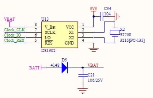
33001 bytes |
| ullix |
Posted - 08/25/2018 : 23:09:20
The RTC itself does not seem to be the problem, because when the time comes back, the time is correct (within 1...3 sec) even when the outage lasted for hours, so the RTC has continued to run.
Somehow it is either the soldered connection of the RTC to the system/CPU, or some issue in the firmware.
|
| the_mike |
Posted - 08/25/2018 : 02:16:34
The RTC-issue reminds me of the old PCs before plug&play was a thing, and a CMOS-Batterie-Failure was common... Everytime the Batterie failed, one had to reset ALL settings in Bios...
So it's my guess, that the RCC doesn't get constant power for running for a reason. Thus the need of resetting Date&Time all the time... Add a little "Firmware not so ready for the RTC" and you have an explenation for this behaviour i think?
(could you test if the RTC gets some power when the 500+ is turned off ? Pin-allocation should be available googling the component..?) |
| ullix |
Posted - 08/25/2018 : 00:58:48
just to underline the issue, the output of GeigerLog after it parsed the history:
# 1057, 2000-00-00 00:00:00, Date&Time Stamp; Type:'CPS, save every second', Interval:1 sec
# 1249, 2000-00-00 00:00:00, Date&Time Stamp; Type:'CPS, save every second', Interval:1 sec
# 1441, 2018-08-24 19:11:51, Date&Time Stamp; Type:'CPS, save every second', Interval:1 sec
# 1633, 2018-08-24 19:14:52, Date&Time Stamp; Type:'CPS, save every second', Interval:1 sec
# 1825, 2018-08-24 19:17:52, Date&Time Stamp; Type:'CPS, save every second', Interval:1 sec
# 2017, 2018-08-24 19:20:52, Date&Time Stamp; Type:'CPS, save every second', Interval:1 sec
# 2209, 2018-08-24 19:23:52, Date&Time Stamp; Type:'CPS, save every second', Interval:1 sec
# 2401, 2018-08-24 19:26:53, Date&Time Stamp; Type:'CPS, save every second', Interval:1 sec
# 2593, 2018-08-24 19:29:53, Date&Time Stamp; Type:'CPS, save every second', Interval:1 sec
# 2785, 2000-00-00 00:00:00, Date&Time Stamp; Type:'CPS, save every second', Interval:1 sec
# 2977, 2000-00-00 00:00:00, Date&Time Stamp; Type:'CPS, save every second', Interval:1 sec
shortly before 19:11h I got the device working. Then I'd left the device alone, expecting a night of measurements.
Only some 20min later the 500+ failed again, and remained in failed state until this morning. With some gentle slamming I got it back to work; but only for a few minutes.
Any idea how this can be fixed? Any places for re-soldering?
|
| ikerrg |
Posted - 08/24/2018 : 12:50:53
quote:
In the last few days I got many dozens (!!) of times the message at the counter "Please set date & time".
I have never seen that problem in my device. Yours is probably a defective unit as you might have already found. |
| ullix |
Posted - 08/24/2018 : 02:15:05
Not enough weirdness with the 500+? Here is more, this time on the Real-Time-Clock (RTC).
The old counters do not have a RTC; they use the CPU to keep the time, which does not go too well. Switch the counters on and off, or do other work, and the time flips forth - or back - by seconds, minutes, days, even decades!
The 500+ does have a RTC (see picture: the 8-legged device north-east of the CPU with the marking DS1302Z, thanks to the_mike for identifying). And it is better, at least as long as it works, which is the catch.
In the last few days I got many dozens (!!) of times the message at the counter "Please set date & time". Well, setting isn't possible: stepping through the date/time-setting menu shows you all zeros for year month day hour minute second, but not one can be changed! Rebooting does not help. Factoryreset does not help. Attempting to set the datetime via GeigerLog does not work - ironically the counter returns the AA byte on the SETDATETIME command, but the datetime is not set.
Removing the battery does help sometimes, but that "sometimes" is probably due to the mechanical agitation, because:
The only thing that helps is slamming the lower-right corner of the counter (where the battery minus is) on the desk.
I guess a loose connection somewhere, aka bad soldering. How is that for hitech?
P.S. such sudden losses of DateTime also occur in long runs, like overnight. As 2000-00-00 00:00:00 is not a valid date, GeigerLog translates this into '2099-09-09 09:09:09'. When you see such a date&time in GeigerLog you know it came from a bug in the counter!
|
| ullix |
Posted - 08/24/2018 : 01:31:17
More weirdness, this time on the threshold.
You can set a threshold, like 100CPM, and direct the counter to only save data to the internal history memory, when the counts exceed this threshold. This works in principle, but:
Pressing the buttons while in the counter's threshold menu I notices ridiculous results of "�Sv" of some 4.3 million, and it could even be downloaded by GeigerLog, see picture.
Image Insert:
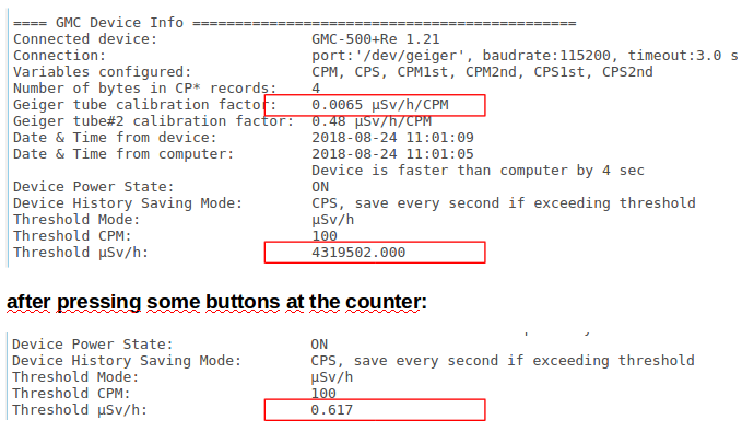
63125 bytes
And that while CPM stayed at 100. After some more button pressing this went away and a more reasonable 0.617 showed.
No surprise when people complain they lost 2 days worth of data, when they used the threshold saving mode of the counter http://www.gqelectronicsllc.com/forum/topic.asp?TOPIC_ID=5396
Please explain, when the calibration factor is 0.0065 �Sv/h/CPM, and the CPM value is 100, why is that calculated to be a "�Sv" mode value of 0.617? Shouldn't it be 0.65 straight?
And why is this "uSv" value fluctuating from 0.61 to 0.63 ??? What algorithm gives different multiplication outcomes from a microprocessor? (let alone none is correct)
And last, but not least: the units are �Sv PER HOUR and mR per hour. It is another level of sloppiness in not getting the units correctly, telling in big letters the lack of scientific understanding.
|
| ikerrg |
Posted - 08/21/2018 : 10:35:08
Sorry, my bad! Yes, I meant anode.
No idea of the quantitative effect of a higher resistance. I suppose that it needs to be confirmed by GQ using their testing units. I think that the avalanche effect of the electrons inside the tube might not be linear with the impedance of the circuit, and therefore the change of the resistance in series might extinguish the current much quicker than expected, reducing the load on the HV circuit. But it is only an speculation, I don't really know!
|
| ullix |
Posted - 08/21/2018 : 01:25:11
@ikerrg: you said cathode resistor but may have wanted to say anode resistor? The GMC devices are cathode sensing (the RadMon+ is too) so there are cathode resistors (RadMon+: about 100kOhm), though I can't see why changing them would possibly make a difference.
I don't even see how changing the anode resistor could make a difference. We have the internal resistance of the HV of 16.12MOhm. The anode resistor is 3M in series with it, which would reduce the current by some 15%. So what?
My guess is that this anode resistor is a remnant of the old Geiger counters, like Stargazer's flat iron type counter with perhaps lethal high voltage. 'Lethal' here would mean its internal resistance is much lower, perhaps (well) below 1M? In this case it is important having an anode resistor that would limit the current flow through the tube, which otherwise might have turned the tube into a light bulb due to a non-extinguishing discharge in the tube?
|
| ullix |
Posted - 08/21/2018 : 01:01:43
@EmfDev: measuring the CPU temperature does have its value, though marketing it as temperature sensor for the environment surely does not!
Now after declaring it as not valid, the proper procedure in the firmware would have been to return a defined dummy value, such as e.g. done in the 300E+ as b'\x00\x00\x00\xaa'. Instead you return something undefined that sometimes looks right and sometimes not.
Another very unnecessary confusion!
I will now remove it completely from GeigerLog. |
| ikerrg |
Posted - 08/20/2018 : 09:44:46
quote:
As for the HV being high when turned off and conencted to USB, it is a flaw in the design and we will look into it and
try to improve the hardware, including reducing the voltage drop at high cpm.
Thanks for looking into it. I would appreciate if you could release any hardware modification that you might decide to implement, so we can improve that in our flawed devices if it is a simple fix (like increasing the cathode resistor). For what we know so far, the 50k CPM reading could have a massive error (>100%). I do not consider fair having to stick to devices that are not working as expected.
|
| EmfDev |
Posted - 08/20/2018 : 08:55:48
@ullix sorry we have decided before to remove this feature as it looks like the built in temperature sensor from the processor
is greatly affected by its temperature(or this temperature is actually for the processor) and is inaccurate. We just forgot to remove it from the documentation.
As for the HV being high when turned off and conencted to USB, it is a flaw in the design and we will look into it and
try to improve the hardware, including reducing the voltage drop at high cpm.
For testing, you can try to increase the high voltage by twisting a potentiometer near the WiFi/ESP8266 module to see if it helps. Remember that the guy from the video was still able to generate 50k CPM under 1 minute with the current hardware.
Also I checked on the changes between your hardware and the newer one
and found that they adjusted the distance between
the small tube terminals and that's it. All other parts
were not changed. |
| ullix |
Posted - 08/18/2018 : 00:02:28
@EmfDev:
The GETTEMP command in the 500+ seems to also have changed. While this is in your document stated to be valid:
24. Get temperature

command: <GETTEMP>>

Return: Four bytes celsius degree data in hexdecimal: BYTE1,BYTE2,BYTE3,BYTE4
	Here: BYTE1 is the integer part of the temperature.
	      BYTE2 is the decimal part of the temperature.
	      BYTE3 is the negative signe if it is not 0.  If this byte is 0, the then current temperture is greater than 0, otherwise the temperature is below 0.
`	      BYTE4 always 0xAA

Firmware supported: GMC-320 Re.3.01 or later
I am sometimes getting 4 bytes that are inconsistent with this (in decimal):
38, 12, 00, 170
The 38 (�C) is way too high, even for a sensor sitting on the board, the 12 is an illegal value within your definition, the 00 may signal a positive temperature, and the 170 is end-of-message.
It is also not an ASCII format text.
What is the new coding in the 500+?
What else has been changed and is now different from what is stated in your document?
|
| Stargazer 40 |
Posted - 08/16/2018 : 15:27:43
Thanks ullix for going through all that and I'm glad you didn't get bitten by the tube. The power supply on the Civil Defense 700 meter is at 900VDC and is powered by a couple D cells. It has been described as potentially lethal and I think I won't be adventurous with either meter. :-)
I did match the response of the CDV-700 meter to that of the GMC-500+, by the way. I didn't use the Cesium spot on the case because it would have read on the low end of the scale where things aren't accurate at all. Instead I used my stack of Th gas mantles and both meters were reading the same 3.25 mR/h when I got done. That's right at 5000CPM for the 500+ and 2000CPM for the CDV-700. I will need to check the specs, but that makes the conversion factor for the 6993 tube .01625. |
| ullix |
Posted - 08/16/2018 : 09:14:50
@Stargazer: you are overestimating the charge this HV-gen can hold. This "103" at capacitor C2 in ZLM's circuit probably stands for 10*10E3pF = 10nF. The same value is used at the RadMon+ design, here actually for 2 capacitors C5 and C6, so 10nF are likely also used at the GMC-500+, albeit only 1 instead of 2. Should only effect the ripple on the HV, not the overall power of the HV-gen.
The RadMon+ works this way: I set it to collect CPM for 60 sec, then it shuts down the HV to save power(!), then collects the temp, press, hum data from the BOSCH sensor, then sends all data via WLAN to an MQTT server (located in California). After all this, which takes about 7 sec, the HV is restarted. This shutdown helps in power saving to allow running the RadMon+ on batteries when using as an outdoor monitoring system.
This picture shows the falling edge of HV after CPM is completed, and the rising edge for the next round of CPM. The latter takes less than 0.1sec for full HV. The signal is measured via 1GOhm to a 10MOhm osciloscop, and it falls to almost zero after the 7 sec.
Image Insert:
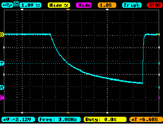
4188 bytes
With the HV gen having an internal resistance of 16.12MOhm, a true shortcut at 400V would result in a current of 25�A. That is 100 to 1000fold less of what it takes to do electric shock harm to a human being. So, I became adventurous and touched the anode with a finger. Nothing. Used two fingers of one hand on anode and cathode. Nothing. Tried the more powerful RadMon+: nothing.
Strange. Though to quote the RadMon+ builder: "Careful! The HV at the screw terminals may now bite when touched." Maybe I have given myself away; it is the "human" part, which matters ;-)
Still, while the electric shock part may not be of concern, the tube is powered upon connection although the counter pretends it is not (while allowing full interaction with GeigerLog). But when the tube has HV, it counts, and thus, is using up its lifetime count budget when all you want to do is charging its battery.
What is wrong with the concept of "OFF" really being "OFF"?
|
| ikerrg |
Posted - 08/16/2018 : 05:39:02
I think the USB cable connection actually powers on the device to be able to charge it. You even have access to the serial port with the device in that state (OFF but connected to the USB). I think it is related to what I asked in http://www.gqelectronicsllc.com/forum/topic.asp?TOPIC_ID=5304 Reply#78 and EmfDev answered in Reply#80 (second paragraph).
It is actually a good thing that you can have access to the serial port with the device in OFF state, because it allows you to reset it or re-update in case of a failure in the firmware update process. But the HV circuit should stay OFF!
I have actually seen a weirder behaviour after updating the firmware with the device OFF (i.e. device off - connect usb - update firmware). When the firmware update finishes, the device resets and stays off (charging), but the speaker starts noticing radiation events in the tubes!
|
| Stargazer 40 |
Posted - 08/16/2018 : 05:08:51
quote:
Originally posted by ullix
Another oddity:
with the GMC-500+ being powered off and unconnected, I plug in the USB cord.
While the device seemingly remains off, and the power switch has not been touched, the tube does get power, some 360+ Volts. Could be an unpleasant surprise when you come into contact with the anode, expecting it to be free of any harmful voltage.
What is a power switch for, if not to switch power?
Could there not be some charge in the system remaining in the HV caps?
Does it appear fixed or does it dissipate. ?
|
| ullix |
Posted - 08/16/2018 : 04:57:03
Another oddity:
with the GMC-500+ being powered off and unconnected, I plug in the USB cord.
While the device seemingly remains off, and the power switch has not been touched, the tube does get power, some 360+ Volts. Could be an unpleasant surprise when you come into contact with the anode, expecting it to be free of any harmful voltage.
What is a power switch for, if not to switch power?
|
| Stargazer 40 |
Posted - 08/15/2018 : 16:48:53
quote:
Originally posted by ikerrg
quote:
I guess I would like to know what was changed between the 3XX meters and the 500/600 meters to get to the max for sensitive tube 4250 uSv/h levels we see on the geiger selection table compared to the 328 uSv/h shown for the 320.
I think I read somewhere that the new meters have a 32 bit CPU, so they can count bigger numbers with the same tube.
One thing is clear: If you want the 500+ to use the SI-3BG tube to measure high radiation close to what is shown in the specs (42 mSv/h), the M4011 tube has to be physically disconnected. And that requires a hardware modification that you are not allowed to do without voiding the warranty. It is a simple switch that has to be accessible from the outside of the cover, and I might include it when I decide to start modifying my GMC-500+ (the SBM-10 tube is still on its way!)
Please, keep us informed when you try to increase the voltage in the HV circuit.
Okay, now I think we are getting somewhere with regard to expectations. How can you advertise numbers of range more than 10 times the GMC-320 in the GMC-500/600. You increase data storage precision from 2 bytes to 4 bytes. I think we have to think a little differently about how GQ might be looking at these counters. They have a sticky in the forum on custom tube usage. In some ways they are providing you a dosimeter with a couple tubes and some decent firmware and an adequate power supply. But changing the storage by doubling the bytes allows for adapting different tubes that can make use of the HV and counting mechanisms of the 500+ and maybe make use of the extra precision and they can market based on a 4250 uSv/h range provided by the storage capacity. The counter as you buy it won't be able to get there, but it may provide a vehicle for you to adapt additional hardware to make more use of the counter increase in precision. Kinda like the DIY Radmon.
What really is needed is a regulated HV power supply that adjusts to the count rate to keep the tube within the working voltage range. These power supply circuits do not provide for that. If GQ could build that kind of power supply into a meter and give a little more thought to two more closely match tubes we might get a two stage meter that fits a lot better all the things we envisioned with the 500+.
When I get my 1Gohm resistors I'll let you all know how the voltage increase works. I do wish that ullix would make these adjustments with his provided meter as he has no investment in keeping it under warranty, and he can keep the data graphing consistent with starting voltage for measurement up near 500V.
|
| ikerrg |
Posted - 08/15/2018 : 13:31:25
quote:
I guess I would like to know what was changed between the 3XX meters and the 500/600 meters to get to the max for sensitive tube 4250 uSv/h levels we see on the geiger selection table compared to the 328 uSv/h shown for the 320.
I think I read somewhere that the new meters have a 32 bit CPU, so they can count bigger numbers with the same tube.
One thing is clear: If you want the 500+ to use the SI-3BG tube to measure high radiation close to what is shown in the specs (42 mSv/h), the M4011 tube has to be physically disconnected. And that requires a hardware modification that you are not allowed to do without voiding the warranty. It is a simple switch that has to be accessible from the outside of the cover, and I might include it when I decide to start modifying my GMC-500+ (the SBM-10 tube is still on its way!)
Please, keep us informed when you try to increase the voltage in the HV circuit.
|
| Stargazer 40 |
Posted - 08/15/2018 : 11:44:07
A couple of comments on my selection process. A good friend acquired a Mazar 9000 meter because it was capable of alpha detection if a couple of passes were made to isolate. It's range is 0.1 to 1250 uSv/h. A very good meter, but not as high specs as 500+ (0-4250 uSv/h for M4011 and 0-42500 uSv/h for SI-3BG). $572.60 USD on Amazon. The Radex RD1212-BT was the other I was comparing. It has Bluetooth and not Wifi. Also a phone app for data logging. It uses an SBM-20-1 tube. It's range is .05-999 uSv/h. Cost is $234 USD. This is used by an former govt nuclear waste/incident manager as his personal pocket meter and supplemented with a Ludlum 3 Survey meter with pancake wand. The Ludlum is $500 plus in the used market.
The 500+ covers the ground of all three of the above and we are learning the actual ranges it is valid for through some serious analysis by ullix and testing by ikerrg. I think it is the most capable meter and the best value that GQ sells. To beat the range for the Mazar 9000 we need to be able to receive from the M4011 1250/.0065=192,300 CPM. I think we know at this point it will not be likely. But if those higher levels are encountered and we use the SI-3BG tube stand alone, 1250/(.0065*70)= 1250/.455= 2750 CPM for gamma and 1250/3.25= 385 CPM for beta may very well be possible, although the HV may not allow either of those count levels. Again we need to adjust the voltage to the max and redo the distance measures of Post #17. GQ's 320 V5 is rated 328 uSv/h. 328/.0065 is 50461 CPM and that is already a reality with the video showing CPMs that high, likely with the M4011. Still, it may be out of the plateau region at that point so maybe not an accurate measure. It may be when all is said and done that the 500+ on the sensitive tube will match the 320 and if much the same in hardware, would be expected. As well the Radex meter may be more capable (if it also doesn't have HV issues) from a value standpoint, but wouldn't trust it out of the box to be able to meet its specs either.
I guess I would like to know what was changed between the 3XX meters and the 500/600 meters to get to the max for sensitive tube 4250 uSv/h levels we see on the geiger selection table compared to the 328 uSv/h shown for the 320. |
| Stargazer 40 |
Posted - 08/15/2018 : 09:53:00
All you say I do agree with, except the other saying that goes without saying is 'Buyer Beware'. I have to say the numbers in the specs sounded good, but really, given the degree to which they are off in actual use, how can you guys not have known something was amiss with them? I did enough research to see that this was a bargain for what I paid. I think it is more of a bargain now. And I don't consider this meter a toy. I consider it a device in which I am gaining more confidence with each bit of analysis presented. I am comparing to meters much more expensive without a second level of data collection capability built in. And now I can determine which to use. (Your extra 20EUR buys you that. Not a bad add for the money when the tube alone is 10EUR all by itself.) You praise the Radmon, but it is a kit that isn't cased and has a lot of flexibility, but is what you make out of it. Same here. Find the limitations of the 500+ (which is what you and ullix are doing) and what it does well and make use of those. I likely will get some 600V coax cable and solder to clips with small hole in side of case and add clips to use with different tubes on that least sensitive side of the meter. Will fashion a wand or add small case to eliminate risk of high voltage in use. Would really like to add a pancake wand but need to watch line losses. And finally certainly interested in higher HV testing with mantles and, of course, I'm interested in GQ's response to these data.
|
| ikerrg |
Posted - 08/15/2018 : 09:36:54
@Stargazer 40: I mostly agree with what you say, although blaming contractors should never be an excuse for a poor job. In any case, I feel slightly cheated by the specifications, because the good value for the money (and better agreement to the specs in http://www.gqelectronicsllc.com/support/GMC_Selection_Guide.htm) goes to the GMC-3XX models. Clearly the GMC-500 series is over-specified and overpriced, and you get nothing but a poorer accuracy on the high sensitivity tube, a poorer calibration capability and an unknown response on the low sensitivity tube. And after the last findings, it even requires physically removing the high sensitivity tube if you plan to do high radiation measurements at any time. For me that is not fair, because they should know the limits of their devices and advertise them as corresponding. If the purpose of consumer products is just measuring background or play with uranium plates, the dual tube device is a nonsense and a way to cheat more advanced people to buy something that is not going to fulfill the advertised specs.
That being said, personally I enjoy the process of testing and researching, and I am learning with ullix�s and my own experiments in the process. If that is worth the extra 20 EUR of the GMC-500+ vs. the GMC-320+, maybe, but not many people will be so keen to pay for something just to enjoy debugging and tuning the system for a private company that is making money with it.
The pity is that, just by reading the RadMon+ manual, GQ could have understood and found most of these issues, and now we should be talking about how to improve the firmware to get the most of the device, not about how to fix the hardware in something so basic as providing the right electrical feeding to the key component (the GM tube).
|
| Stargazer 40 |
Posted - 08/15/2018 : 07:48:45
The other comment I would make regarding the overall utility of this meter (and all of GQ meters of similar design) is that you both as users are probably in top 1-2% of users with regards to technical expectation. I have strong interest in background radiation and especially alpha from radon gas. I have a purpose built meter for that. I expect given the US map display GQ provides that many, many other users are getting good value in seeing their background responses posted along with other GQ users on the map. I think that for many, playing with mantles and ore samples and even radioactive glazed plates meets a traditional educational need that the meter performs quite nicely. If however you're doing high level laboratory data collection and analysis, or in the field where high levels in some areas are dangerous or lethal, are you really going to trust your health or results to a $125USD meter? Seriously? As the_mike said, in those situations it's worth it to spend (much) more or leave it to NC personnel. As a consumer product, GQ has built some very nice stuff. My expectations as both someone interested in those items above, and as someone interested in the all hazards emergency response side of things are being met and reinforced by all the work that you both have put so much time in. GQ has demonstrated the commitment to improving our understanding of the meter's response again and again in the short time I'm owned my meter. You can criticize the lack of testing, and the characterization of the capabilities, but I think that those inconsistencies are based more on the individual components and not the sum of the whole (which honestly they should be based on). I think in general that I got what a paid for and paid a lot less than for other meters that have a whole new set of issues that would need to be understood. I like the Apostle Paul's comment regarding Church doctrine = (roughly paraphrased) Test everything, keep the good, toss the bad. There is a lot of good here for the money. I remain impressed with GQ's involvement, and I do not fault them overly much for not wringing these meter's actual capabilities out. I am confident that they are relying on the design engineers claims that may not even be more than subcontractors in the overall scheme of things. As I said, I think we're very close to a confident assessment of the limitations of the 500+. I have learned a great deal and thank you both, no matter what the further response of GQ. Truly, really fun stuff. |
| Stargazer 40 |
Posted - 08/15/2018 : 06:59:04
Yes, I know that both graphs are entwined in the response. I just think we are not on the same playing field when we are characterizing the M4011 response in the GQ meter while doing so with the Radmon HV power supply. By cranking of the HV to the max in the GQ meter and then redoing the distance measures of the thorium mantles I think we will get a final solution for what those count levels might be for this meter to stay on the plateau. And I think that even with a non-linear response when voltage higher and lower than plateau there still is some useful information. |
| Stargazer 40 |
Posted - 08/15/2018 : 06:52:16
Am I reading the schematic correctly when I say that to increase HV voltage we want to turn this pot counter clockwise to increase the resistance to ground and increase the voltage the transister sees at input? |
|
|