| T O P I C R E V I E W |
| ikerrg |
Posted - 08/03/2018 : 14:26:27
I’ve been searching for some information about the SI-3BG tube while trying to back our findings of the very small sensitivity in the different experiments (KCl bag, uranium glazed plate, etc.).
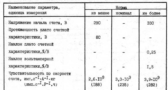
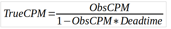
The best approximation backed by data that we have is the experiment in http://www.gqelectronicsllc.com/forum/topic.asp?TOPIC_ID=5322 (mainly for beta particles). The estimated sensitivity of the SI-3BG tube is only 0.32258 CPM/(uSv/h), compared to the 153.84 CPM/(uSv/h) of the M4011 tube. That results in the SI-3BG being about 477 times less sensitive than the M4011 tube, far from the advertised 29.84 calculated by using the default sensitivity in the GMC-500+ firmware (1/0.194=5.1546 CPM/(uSv/h)). After reading the information in https://sites.google.com/site/diygeigercounter/gm-tubes-supported I had the idea to find some real data for the SI-3BG tube. I found that in http://www.gstube.com/data/2486/ , but the translated information in English just made no sense. So I decided to use a Russian virtual keyboard to try to translate the bad scanned documents to English (if there is any forum reader with Russian knowledge, please, help to properly translate these documents). I used a little bit of my Cyrillic alphabet knowledge to quickly find the interesting bit (translating all the documents would have been too long to me), and then I did the translation using Google. I plan to keep finding information in the documents, but here is what I found until now in one of the tables:
Image Insert:
50318 bytes
The key information is in the last row. It says something like:
quote:
Counting sensitivity, pulses/s*A^-1*kg (pulses/s*R^-1/h)
First column: Not less than 2.6x10^9 (188)
Second column: Nominal 3.3x10^9 (235)
Third column: No more than 3.9x10^9 (282)
The numbers in brackets are in the units CPS/(R/h), something that we can easily translate to CPM/(uSv/h) by multiplying by 6 and dividing by 1000. Therefore, the numbers are 1.128, 1.41 and 1.692 CPM/(uSv/h) respectively. When we compare these numbers to the ones obtained from experiments, the results are in the right direction. The SI-3BG tube is between 153.84/1.692 = 91 and 153.84/1.128 = 136 times less sensitive than the M4011 tube! And that is real calibration data, which probably is only for gamma radiation given the very high radiation purpose of the SI-3BG tube. The tests that we did with KCl (which increases the gamma percentage in the radiation field) or with the shielded uranium glaze (again, more gamma percentage) showed that the ratio between the tubes was smaller than 477, about hundred-ish (http://www.gqelectronicsllc.com/forum/topic.asp?TOPIC_ID=5278 ), which aligns better with the calibration found in the Russian document (therefore for gamma radiation?).
In summary, the calibration data found in the attached Russian document together with several real life experiments seem to invalidate the calibration factor of 0.194 (uSv/h)/CPM used by default in the GMC-500+. The sensitivity of the SI-3BG tube is so small compared to the M4011 that their combination in one device is simply not very useful. A tube like the SBM-10 (http://www.gstube.com/data/2396/) would have been much more appropriate for this dual tubed device.
That being said, the recent possibility in the GMC-500+ firmware to display and record just the reading of each tube separately allows the user to find the independent calibration factors if a high enough known radiation field is available (different for beta and for gamma). And using the estimation of “dead counts” on the M4011 tube (https://sites.google.com/site/diygeigercounter/gm-tubes-supported ), it can behave linearly in a much bigger range than what most of the users need. By the way, it would be interesting if the calculation of the CPM extrapolation would be available as an option embedded in the firmware of the GMC counters! (by using a customizable dead time for the M4011 tube) @EmfDev, that could be a possible firmware improvement for all the GMC-XXX devices!
|
| 73 L A T E S T R E P L I E S (Newest First) |
| ullix |
Posted - 11/09/2018 : 01:31:03
quote:
On the other hand, your measurements with shielded KCl (ratio of 72 for gammas) have a big uncertainty because the radiation was too weak compared to background. Even if you got a good Poisson distribution, that could be the convolution of the two distributions from the source and the background, and that would also be Poisson.
It is not a convolution (or folding), because this term is used for something else, see Wikipedia.
It is simply that the sum of two pure and independent Poisson distributions is a pure Poisson distribution itself!
But this has the benefit that the sum of the averages of two Poisson distributions is equal to the average of the summed distribution!
So, in order to reduce any uncertainty, you'll have to measure long enough to accumulate sufficient counts for each of the two conditions, like background-only, and background-plus-source.
Remember that the StdDev of a Poisson distribution is the square root of its average. And that the StdError is the StdDev divided by square root of the counts (for independent counts). You then compare the two signals plus/minus their StdErr. If the error bars of the signals do not overlap, you can make the case to have two separate disributions.
My attempt to distinguish between two very similar distributions was needed when I tried to measure the radioactive property of bananas. The "banana dose" is often cited, but very difficult to measure. See my article "Going Banana" https://sourceforge.net/projects/geigerlog/files/GeigerLog-Going%20Banana-v1.0.pdf/download
|
| Stargazer 40 |
Posted - 11/08/2018 : 05:03:53
Give you guys some interesting concept to explore and a wonderful world of scientific adventure dawns. GQ, please note that the .1 MeV lower limit you specify under detectability in the 500+ specs is about to be challenged by half.
I bought box of six smoke detectors ($22USD) on Ebay. Am tearing them apart to do essentially the same thing as far as amassing larger point source. No sure how easy to get the tiny cup of stuff separated from larger cup, but will tackle as needed.
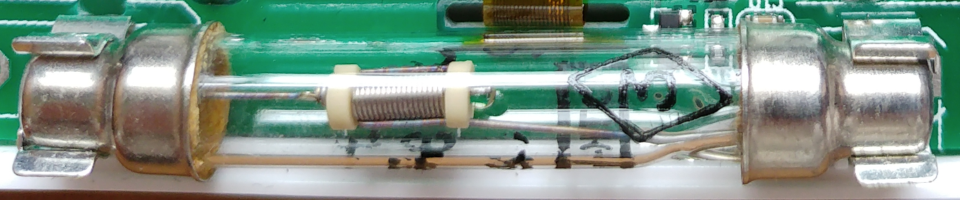
And kudos ikerrg for noting the tiny tube inside the coil. I've tried to understand what kind of apparatus would be using a 'spring' to keep things taut inside that glass tube. Should have used a magnifying glass.
|
| ikerrg |
Posted - 11/08/2018 : 02:45:55
That is true. I do not think that it is only the size/volume of the tube what matters, but also the construction, and the M4011 has a very thin metallic layer on the glass internal surface (it is even transparent!) to interact with the gammas, but the SI3BG has a thick metal enclosure. The gammas are not detected directly, but via an indirect process of kicking electrons in the tube’s shield. And I still think that the 1.4 MeV gammas are not well detected by our tubes, as they have such a high energy that they are almost transparent to them, so I do not know if what you detected after the aluminium shielding was mainly bremsstrahlung radiation from the betas. On the other hand, your measurements with shielded KCl (ratio of 72 for gammas) have a big uncertainty because the radiation was too weak compared to background. Even if you got a good Poisson distribution, that could be the convolution of the two distributions from the source and the background, and that would also be Poisson. I need to do this for lower energy gammas, and hence what I am going to explain now:
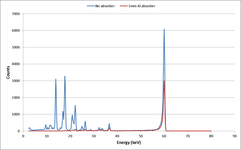
I am into a process to understand much better all this. I have contacted a guy at work that knows a lot about radiation, atomic decay, shielding, etc. He also has a gamma spectrometer (for low energy gammas), and that is how I plan to take a very scientific approach to understand the response of the tubes. The problem is that I need time that I do not have to go through all this process of understanding, and my weekends are quite booked! He has measured the gamma spectrum of Am-241, with and without a 3 mm aluminium absorber that makes the radiation almost monochromatic. I have confirmed that our tubes can detect 60 keV gammas, so that is good. Because 60 keV is conveniently close to a change in the slope of the mass attenuation coefficient (https://physics.nist.gov/PhysRefData/XrayMassCoef/ElemTab/z13.html ) the absorber strongly attenuates the low energy lines but only reduces the 60 keV line by about half. There are no emissions above 60 keV from Am-241 so this is the complete spectrum. The low energy lines are coming from other compounds in the Americium oxide alloy (including gold!).
Image Insert:
48725 bytes
I am in the process of combining several Am-241 pellets to create a more powerful gamma monochromatic source. As it is a point source, at some distance the radiation can be considered homogeneous (and the air does not considerably attenuate the gammas) so I can compare the response of both tubes to single energy photons. I plan to record the radiation for many hours until the statistics are reliable. That will give us a unique ratio for photons at that energy. Stargazer_40 has many other sources, which if correctly shielded they can be used to get the same number at different energies. My guess is that for the same intensity source (e.g. 30 kBq), the tubes are going to be much more sensitive to the lower energy gammas, and that is why Am-241 is much better to get that ratio than KCl (besides the higher specific activity due to the much smaller half-life).
For the dose calibration (uSv/h) for the monochromatic gammas, I still have to think a lot about it, but we can use the mass attenuation coefficients in https://physics.nist.gov/PhysRefData/XrayMassCoef/ComTab/tissue.html and convert that to Gy/h (1 MeV=1.6e-13 J) of energy absorbed in the tissue. For photons, Grays and Sieverts are equivalent.
|
| ullix |
Posted - 11/08/2018 : 01:25:38
 we surely can't complain they were hiding it from our eyes! Well observed! But then all data sheets that I found were misleading. we surely can't complain they were hiding it from our eyes! Well observed! But then all data sheets that I found were misleading.
Now assuming that the volume of the tube is the dominant factor determining the gamma sensitivity, and comparing with the M4011 tube, we get (my measurements/estimates):
M4011: sensitive length: 71mm, diameter: 11mm, wall thickness:0.5mm ==> inner vol= 5.58ml
SI3-BG: sensitive length: 10mm, diameter: 3mm, wall thickness:0.5mm ==> inner vol= 0.031ml
The ratio is 178. Whatever the true ratio - it will be a rather big number.
|
| EmfDev |
Posted - 11/07/2018 : 16:54:07
That makes sense. That explains the very low sensitivity and fast recovery preiod. |
| ikerrg |
Posted - 11/07/2018 : 14:16:13
By the way, have you noticed that the size of the SI-3BG tube is actually very small? The tube is what it is inside the glass bulb, not the glass bulb itself (which only contains the gas for ionization). The anode and the cathode are connected to the external terminals by two welded wires, but the tube itself is only the small chamber that looks like a wound wire inside. Therefore, the size is ridiculously small, and also the active area to interact with radiation (much smaller than the SBM-21), resulting in a much reduced radiation sensitivity. Its sensitivity to betas is even worse because the thick wire that encloses the chamber is shielding most of them (while the gammas can go through it). This close inspection explains the measurements shown by ullix and myself when we started testing this tube, where the ratio of sensitivity between the M4011 and the SI3BG tubes was much higher for betas (about 377) than for gammas (about 70).
Image Insert:
1097394 bytes |
| ikerrg |
Posted - 09/11/2018 : 04:32:10
Good one, though tacky and therefore suspicious if they open my hand luggage. |
| ullix |
Posted - 09/11/2018 : 04:28:26
No need for a screwdriver, just a rubber band around the two case halves! |
| ikerrg |
Posted - 09/11/2018 : 03:22:41
It might be pushing too much to use a screwdriver inside an electronic device while in the airport! Next time I will be in the same airport as in my first trip (London) and I plan to measure the same Xray machine again, to be totally consistent with the first measurement. Hopefully I will have the hardware switch installed and I will be able to do the measurement easily ;)
The flight was going north, I did only the opposite trip.
|
| ullix |
Posted - 09/11/2018 : 03:14:12
Nothing to add. I agree with the conclusions.
I am very surprised about the 1-sec-only x-ray pulse. Seems like my explanation for the 3 1/2 peaks in your previous voyage was correct - it was the recurring collapse and recovery of the high voltage!
I am a little bit surprised about the "high" count rate during flight. After looking at moving average - was it again a flight going south?
Here the 1st tube would have been nice, not the least to finally confirm ratio between the tubes. Next time take the tube with you and mount it while you wait for boarding.
As it is the 500+ is a dud.
|
| ikerrg |
Posted - 09/11/2018 : 02:52:13
Hello again,
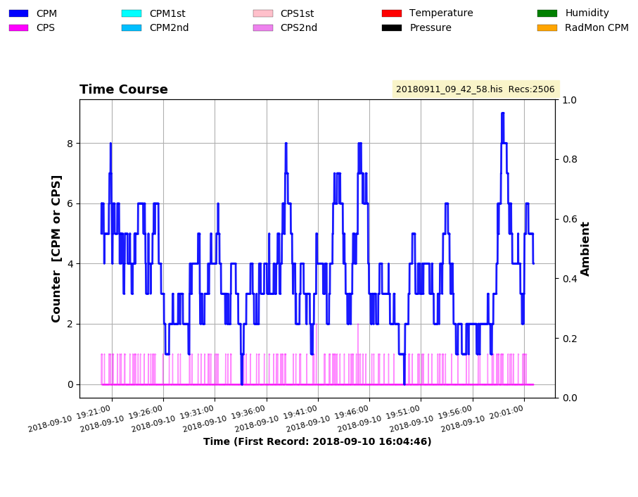
Yesterday I travelled again by plane with my GMC-500+ in the cabin (please, refer to reply #54 and #55 in this thread for information about the previous plane trip). This time I had physically removed the M4011 tube, so all the time the data comes from the SI-3BG. That hopefully avoids the HV circuit power limitation when measuring very high count rates in the M4011. The data is in https://www.dropbox.com/s/l7x5pevt9lw1l4k/20180911_09_42_58.rar?dl=0
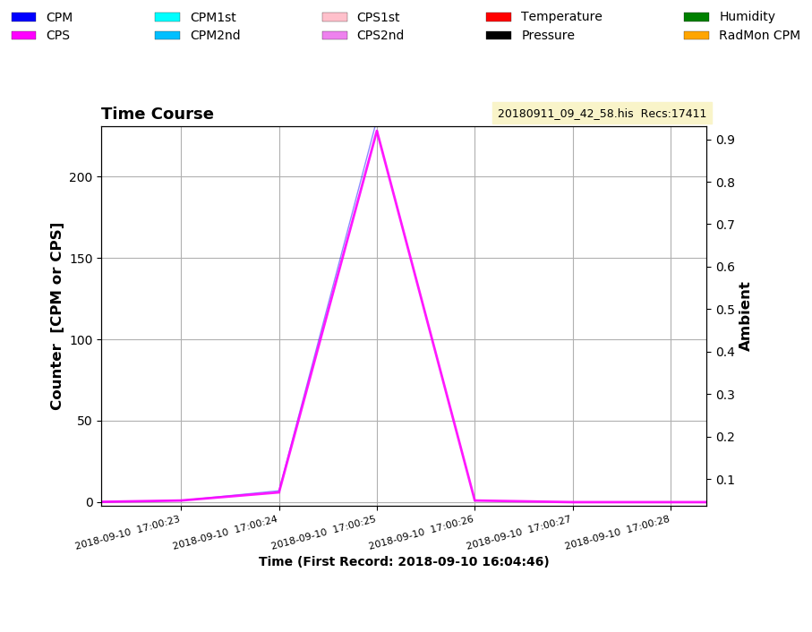
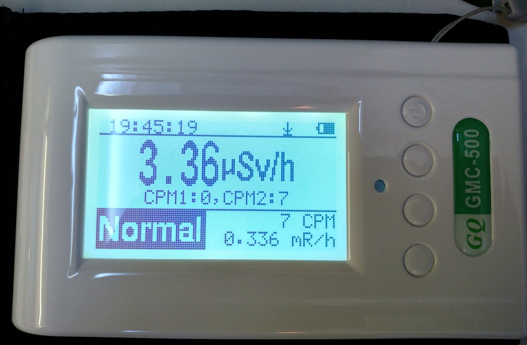
So, I fixed the 500+ in tube 2 mode and measured every second. When I passed the Xrays in the airport security, I got a 228 CPS clean peak (almost completely contained in only 1 second), in contrary to what I measured last time (reply #55).
Image Insert:
56124 bytes
That number of counts in the SI-3BG tube indicates a very big radiation. If translated to what the M4011 would have measured in the same conditions (using the most probable sensitivity ratio between tubes of 0.48/0.0065 = 73.85 as ullix obtained in pure gamma experiments), the M4011 would have measured 16837 counts in that second. We know that the figure is impossible in the M4011 if we consider a dead time of 200 microseconds (ideal max. of 5000 CPS), but what I measured was much lower (2279 CPS), and the peak was not clean at all (with peaks and valleys that could mean a problem with the HV circuit). I have to note here that the airport was not the same as before, and therefore the Xray machine was not the same, and also not the way/speed the GMC-500+ was scanned in the machine. In any case, my point is that the data in reply #54 looked weird and probably affected by the high current consumption of the M4011 in the HV circuit of the GMC-500+. Therefore, the new measurement must be an accurate reading of the radiation burst in the Xray machine (228 CPS cannot draw too much current from the HV circuit), and this is why we need a hardware switch in the GMC-500+ to make it a useful device at high radiation levels as indicated in the specs (currently it is useless without removing the sensitive tube).
About the flight, we already knew that the SI-3BG is quite insensitive and not very well suited for the radiation levels in an airplane. The data is consistent with the previous flight though, as the M4011 was not playing an important role reducing the HV circuit voltage at 37000 feet.
Image Insert:
78309 bytes
Image Insert:
111659 bytes
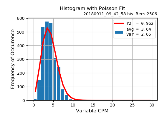
The Poisson distribution of the CPM (converted from the measured CPS) during the steady flight at 37000 feet does not look too bad, given the short measuring time (about 45 min).
Image Insert:
34941 bytes
Please, ullix, feel free to do your magic with the raw data to get more interesting conclusions.
|
| ikerrg |
Posted - 08/24/2018 : 12:42:35
Thanks ullix. I have tested rc24 and it is exactly what I expected. Now we can calculate the statistical analysis in CPM or CPS from data recorded in CPS to the internal memory. It is very useful for the data of my last flight, where the information recorded from tube 2 alone (in the middle of the flight) is not very useful to be analyzed in CPS, but it approximately fits a Poisson distribution in CPM.
Data from 2018-08-17 17:03:26 to 2018-08-17 17:15:44
Image Insert:
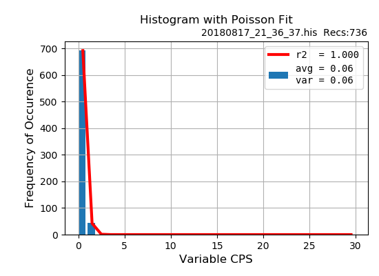
32092 bytes
Image Insert:
32279 bytes
I don’t think I will ever record to the internal memory in the combined mode (tube 1 + tube 2), because as you said, the sum of both counts is a nonsense. But by selecting only one tube, the GMC-500+ only records the CPM or CPS of the selected tube, so the data is totally meaningful.
|
| ullix |
Posted - 08/24/2018 : 02:56:59
Thanks for the idea. Once I realized it is freakin' simple to implement (5 lines of code) I put it together.
When you download the history, the data are now diverted to either the CPM or the CPS column. When CPS, then the cylce time is 1 sec. So I create a CPM out of CPS by summing up the last 60 CPS values, and you get now the two data columns CPM and CPS.
Obviously there is no meaningful equivalent of going from CPM to CPS, as CPM here is recoded only once every minute.
Further, you can use a formula interpreter to scale your input data. I needed it to calibrate my temperature (like: T_new = T_old - 0.6), but the interpreter is much more powerful. You can use it to implement a dead time correction on the counts (see config file, topic 'scaling'). Though I don't recommend it. If you use it, try it on CPM and CPS; these are nonsense values anyway, as they are the sum of both tubes.
P.S. available for download as rc#24 under testing https://sourceforge.net/projects/geigerlog/
|
| ikerrg |
Posted - 08/21/2018 : 10:20:54
quote:
But if had measured CPM every second, you could get the CPS signal by a quasi differentiation of the CPM signal.
Yes, that is valid for signals sampled using GeigerLog, where you read the CPM every second, so taking the derivative would result in the CPS data (with a delay). But when logging to the internal memory, you can only store the CPM every minute, or the CPS every second, and that was I was referring to when I said that “you cannot get CPS from CPM, as you have already lost the information of what happens every second”. So the only way to not to lose any information from the signal is by reading the CPS every second and then mathematically convert it as needed (no conversion for short timed sources and do a CPS to CPM conversion for long reading times). I know that it is better to directly store in CPM not to waste storage memory, but if you have sudden sources of quickly changing radiation, the CPS mode should give you all the information.
So, is it possible to implement in GeigerLog a conversion between CPS and CPM so you can process the data statistically as if it was logged in CPM? I am only trying to get the most of the internal storage options of the device. When reading with GeigerLog, the possibilities are much broader.
|
| ullix |
Posted - 08/21/2018 : 03:21:31
quote:
The tubes are secured by some white plastic strips, that you have to cut to take them out. Now that you have opened the device, do you think the strips are needed?
I guess when you cut the plastic strips and then smash the counter to the floor, the only thing to survive are the clamps holding the tube
quote:
From my point of view, you cannot get CPS from CPM, as you have already lost the information of what happens every second, but you can get the CPM from CPS by summing the CPS in a window of 60s every second, and get exactly the same data as if you had recorded the information in CPM. That is exactly what the GMC does on the fly on screen (it is easy to see when you switch it on and it starts accumulating counts and calculating the CPM). Multiplying the CPS by 60 as in you example is not the real CPM, as you are assuming that the CPS value is constant during 60 seconds. If that is true, GeigerLog should be able to convert a CPS recorded file to CPM and do the statistical analysis of the data in CPM.
No. Don't confuse the units with the measurement schedule. 1 CPS=60CPM=86400counts per day, and all is valid. The problem is that you have a high scatter, which is exactly the same whether expressed in CPS, CPM, or CPDay.
You can smooth that by integrating (summing up) the counts over periods longer than 1 sec, like 1 min, 1 h, 1 day or even longer. You don't even need to measure in strictly consecutive intervals, like 1 sec. For a truly random signal you can take measurements of 1 sec e.g. every minute for 1 hour and get the same result, provided you have NON-CHANGING source. (Clearly not the case passing airport security).
The GMC counters sum up all events for a minute for CPM, which is why it takes 1 min to get a stable signal. You could do it differently and estimate CPM from CPS and iteratively approach the very same end value.
Sure, doing a CPS every second, and then do a Moving Average with 60sec time constant would give you a CPM curve, very similar to what you would have gotten by doing CPM in the first place.
But if had measured CPM every second, you could get the CPS signal by a quasi differentiation of the CPM signal.
But select the appropriate scheme for your measuring situation, CPS, CPM, CPDay. Inappropriate is e.g. updating the World-map with background values every 2 min.
|
| ikerrg |
Posted - 08/20/2018 : 07:37:32
The tubes are secured by some white plastic strips, that you have to cut to take them out. Now that you have opened the device, do you think the strips are needed?
From my point of view, you cannot get CPS from CPM, as you have already lost the information of what happens every second, but you can get the CPM from CPS by summing the CPS in a window of 60s every second, and get exactly the same data as if you had recorded the information in CPM. That is exactly what the GMC does on the fly on screen (it is easy to see when you switch it on and it starts accumulating counts and calculating the CPM). Multiplying the CPS by 60 as in you example is not the real CPM, as you are assuming that the CPS value is constant during 60 seconds. If that is true, GeigerLog should be able to convert a CPS recorded file to CPM and do the statistical analysis of the data in CPM.
I'll check you new release candidate.
|
| ullix |
Posted - 08/19/2018 : 23:44:41
Looking forward to more flight data!
Though I wouldn't bother with building in switches; may only be cause for some unexpected electrical disturbance. Plopping the tubes in and out is just as easy. I suggest to use the 2nd tube as only tube for security, and 1st tube as only tube during flight.
I don't understand your question. I suggest you download latest rc#23, in case this has something to do with the parsing of the history data.
But you don't have a choice whether to Poiss analyze by CPM or CPS; you MUST use the mode the data were recorded in.
Examples:
data were recorded as CPM, like 112, 117, 94. In CPS this is 1.8, 1.9, 1.5. This could never be from a Poisson distribution, as Poisson is based on integer-only values! Think of the people in an ice cream parlor, see Potty Training.
data were recorded as CPS, like 7, 8, 9. As CPM this is 420, 480, 540. This also can never be from a Poisson distribution, as the values e.g. 421...479 cannot exist, but Poisson gives them non-zero probabilities to exist!
The old GeigerLog recorded everything as CPM, and so for an original CPS recording you had to switch the interpretation of the data. Then GeigerLog divided all data by 60 on the fly, without telling much about it. This is no longer necessary as GeigerLog automatically knows the recording mode.
|
| ikerrg |
Posted - 08/19/2018 : 10:02:53
Many thanks for the detailed analysis, ullix.
quote:
I have circled two points marking beginning and ending the flight at cruising altitude. You see that the later circle is slightly lower than the earlier one. This is typical when you go from northern latitude towards the equator. So, a flight originating in the UK, going south, duration 1h 30min: Manchester to Paris?
I never thought about that. You can work as a CSI! Yes, the radiation at the same altitude is higher on the poles and lower on the equator, so you are spot on! I could even say that the radiation has more gamma close to the equator and more particles close to the poles due to earth's magnetic field, but that is more arguable. I love when science and knowledge are so powerful to even predict those details! However, you missed the cities ;) It is actually London to Bilbao.
About the XRay machines: I supposed that the peaks happened because of the different position of the trays in series inside the XRay machine and in the belt. I’ve seen them stopping to take the picture, while the previous and the preceding tray are still part inside the machine, with the lead curtains on them. So they could be half exposed, I don’t know. It is a pity, because some time ago I would have been able to have access to one of those with some freedom to have the GMC scanned several times in different recording modes. But now I can’t, so I will use my frequent plane trips to test the 500+. Next time I will be recording with tube 2 in CPS. And if we find something weird (like the possibility that the tube 1 is sucking the HV circuit because it is still connected), the following time I plan to add a switch in series with tube 1 to be able to physically disconnect it. That needs some drilling on the plastic case, so I have to think about the best way to do it in an elegant way, so my device does not become “suspicious” in the airport. If you have any other suggestion for my next trip, you are more than welcome! I am still focusing in understanding the tube 2 response, because we already have data of people flying with a GMC, but never with the dual tubed GMC-500+.
And I have a question about GeigerLog. In a previous release candidate (at least in geigerlog-v09.08-ReleaseCandidate#2) I was able to read a CPS recorded file (internal memory download) and GeigerLog did the calculations to show it in CPS or CPM mode, and therefore show the Poisson plots and everything else for both types of data. In the newest versions, I can only get the moving average in 60 seconds (for me is the same as a CPM mode), but I didn’t find how to statistically analyze it in the same way. Has that been changed for a reason? I am not as knowledgeable as you in statistical analysis, so it might be a stupid question.
|
| ullix |
Posted - 08/19/2018 : 08:00:00
Very nice data!
And yes, going through airport security is the best reason to switch the counter to CPS, because:
1) you want high time resolution
2) you get enough counts to make this viable
The picture shows the 25 seconds of the counter going through the x-ray scanner. Strangely, only 24 data points were recorded. Looks like the CPS cycle takes a bit more than 1 sec, and this accumulates over time to one lost data point?
A total of some 10600 counts were collected in that time, equiv to CPM=25000. Had the counter been set to CPM recording, this would have all gone into a single data point, or at most shared between 2 data points!
You do see the 4 bumps in the time course, 3 big ones and 1 little one.What was the cause for this?
Image Insert:
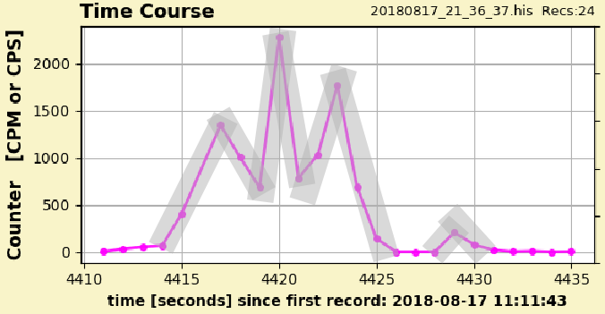
41916 bytes
First though is this is part of the normal scatter you see CPS recordings. However, remember the Poisson nature of the count distribution (if not, Potty Training is your friend!) The StdDev is sqrt(Counts), and within 2 StdEv there are 95% of all counts to be expected. At CPS=1000 the root is 32 (3%), and thus almost all counts should be within a band of +/-100. This is roughly laid out with these grey, transparent bands around the magenta lines. And you see that even if the counts were scattered all over the grey bands, the peaks would not disappear; they are real!
Do these X-ray scanners have multiple tubes, like 3 big and a small one? I don't think so.
Did the x-ray operator saw something suspicious in ikerrg's bag, and moved the belt back and forth? 3 times back and forth? Possible, but I have never observed that in any airport.
Another possibility: at the 1st peak the counter HV dropped due to the overload, reducing the count rate, thereby allowing the HV to recover, which resulted in the next high peak, and more 2 repeats.
I'd love to play with these scanners 
Next, the flight.
Image Insert:
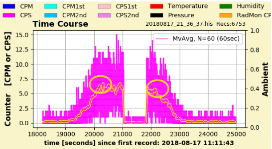
78291 bytes
Now the StdDev is sqrt(5) and that is almost 50%, not 3% as above, and we see all the scatter. But not all is lost. GeigerLog has the Moving Average function, and when set at 60sec the resulting yellow-framed curve is about what CPM would have given us. You can nicely see the ascending and descending part around the flight at cruising altitude (interrupted by the test of the 2nd tube).
I have circled two points marking beginning and ending the flight at cruising altitude. You see that the later circle is slightly lower than the earlier one. This is typical when you go from northern latitude towards the equator. So, a flight originating in the UK, going south, duration 1h 30min: Manchester to Paris? |
| ikerrg |
Posted - 08/18/2018 : 00:40:27
Hello,
Yesterday I travelled by plane with my GMC-500+ in the cabin (by the way, no problems at security). So I decided to be the entire flight monitoring and testing! The flight was too short (1h 30’) to gather some statistically meaningful information (ullix could tell me), but we can consider these results another approximation to the complete understanding of the SI-3BG tube. I couldn’t connect the GMC to a laptop, so the recorded data comes from what it can save in the internal memory. Before the last firmware update, I wanted GQ to change the firmware to save the independent counts of both tubes in the internal memory, but they didn’t want to, so we are still limited to store the counts of either one tube or the other tube (or the nonsense sum of both tubes). The data is in https://www.dropbox.com/s/vlq4zkk8ee2rnhf/20180817_21_36_37.rar?dl=0
So, I set the 500+ in tube 1 mode (no sum of counts!) and measure every second. I know that CPM is better for statistics, but the recording time was not going to be long, and I wanted to see with good detail the security XRays!
I went through security at 12:24, and the readings are amazing! I couldn’t go again through the security screening (obviously) with the tube 2 selected, but the next time I plan to have the tube 2 recording instead of tube 1. The peak reached 2279 CPS!!. If the next time I only select tube 2, according to what we know now, the HV circuit could not have enough juice for both tubes, so the SI-3BG might not count sensible data. Or because it is a very quick effect in a few seconds, the capacitors can sustain the voltage level. Who knows what happens inside the XRay machine!
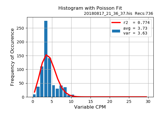
The take-off was at 16:30, and you can see how the radiation increases until we reached an altitude of 37000 feet at 16:45. From there until 17:01 I was recording with tube 1. The average of that period is 5.83 CPS (or about 350 CPM) and the graph of the Poisson distribution in CPS looks about right.
Image Insert:
99388 bytes
At 17:01 I selected the tube 2 in the menu, and I changed back to tube 1 at 17:14, so all the data recorded during that period belongs to tube 2. Here the CPS is so low that the distribution is not Poisson shaped anymore. In the latest GeigerLog RC#22 I didn’t find how to convert that to CPM data (only the moving average in 60 seconds can be plotted), but in any case the recording time is so small that it would not be very meaningful anyway. The average is 0.06195 CPS, or 3.72 CPM.
At 17:15 I activated the tube 1 again and then we started descending and landed.
The data in both approx. constant radiation periods at 37000 feet, one recorded with tube 1 and the other with tube 2, can be used to compare their response to the same radiation. In this case, the radiation is cosmic rays and their atmospheric daughter products, so probably mainly gamma and some high energy particles. The ratio between tube 1 and tube 2 is about 94, which again roughly confirms the results of other experiments. It is clear that the SI-3BG is optimized to detect high intensity gamma radiation! I can’t wait to see the reading of the security XRays in tube 2!
I don’t have time to analyze this in more detail. Any comments and suggestions are welcome!
|
| ikerrg |
Posted - 08/10/2018 : 12:55:19
OK, thanks for the clarification. |
| EmfDev |
Posted - 08/10/2018 : 12:07:44
@ikerrg, that's correct. That's the second checkpoint using the 2nd calibration cpm (30000CPM)
It will always go to the 3rd point which is weighted you change
the calibration to the above.
|
| EmfDev |
Posted - 08/10/2018 : 12:02:53
Yes correct. 30000 is just the default. |
| ikerrg |
Posted - 08/10/2018 : 12:02:17
I am not so sure, bearing in mind the condition:
if ((CPM1 < SOME_TRHESHOLD1) & (CPM2 < SOME_TRHESHOLD2)), then use tube1CPM
where some_threshold2 = (1.5*some_threshold1/tube2Weight)
Could you check that?
|
| Stargazer 40 |
Posted - 08/10/2018 : 11:57:11
So the 30000 CPM beginning of transition zone was only that the 2nd calibration point counts caused the transition software to kick in in the firmware. That number was not hardwired into the firmware. Very good. |
| EmfDev |
Posted - 08/10/2018 : 11:34:26
You can change the calibration 1 and 2 so that it always uses the weighted. The only problem is it won't fit to the hardware
so you need to clip it outside.
Calibration 1 ==>>> 1 CPM to 0.0065 uSv
Calibration 2 ==>>> 1 CPM to 0.0065 uSv
Calibration 3 ==>>> 1 CPM to 0.0065 uSv
this will always use the weighted formula with stdv = 1 and tube1weight = tube2weight = 1 |
| ikerrg |
Posted - 08/10/2018 : 10:52:44
Good luck! The M4011 is much longer than the SI-3BG. That probably needs clipping some connectors on the PCB. And with the current firmware algorithm there would be no correction until you reach more than 30000 CPM (configurable), where the error due to the non-corrected "dead counts" is much more than the additional accuracy (if any) that you can get from a second tube. |
| Stargazer 40 |
Posted - 08/10/2018 : 09:38:00
quote:
Originally posted by EmfDev
I think some SI-3BG are more sensitive, even have some can maybe generate counts with background radiation. But for the 500+ units, the tube 2 should be a really low sensitive tube. But now with the new, you can put a same sensitive tube(M4011) and use both as weighted average for more accurate readings.
So you mean that we could place a second M4011 into the 500+ and weight each equally and get better readings with narrower +- error? |
| EmfDev |
Posted - 08/10/2018 : 08:53:17
I think some SI-3BG are more sensitive, even have some can maybe generate counts with background radiation. But for the 500+ units, the tube 2 should be a really low sensitive tube. But now with the new, you can put a same sensitive tube(M4011) and use both as weighted average for more accurate readings. |
| ikerrg |
Posted - 08/10/2018 : 08:39:19
Sorry, I did not remember that information. This threads are becoming enormous! OK, so it seems that you made the SI-3BG work the same way as I did, not more than 14-16 CPM. However, in this video I posted before, somebody got some interesting CPM from the SI-3BG: https://www.youtube.com/embed/SwIHr2Qd42o?rel=0 . I do not understand that!
Yes, the M4011 is expensive, much more than the SBM-20. |
| Stargazer 40 |
Posted - 08/10/2018 : 06:41:47
From Post #9 in your High Radiation from Plate thread:
'I have a few of the old Thorium laced Coleman mantles in original wrapping. Three packages of two stacked with detector on top gives 4700 CPM from tube 1. Times .0065 is 30.55 uSv/h. Tube 2 reported 14 CPM and to give same 30.55 requires conversion factor of .458 CPM/uSv/h, not the factor I calculated from the tube specs and 2/3 of what ullix reported from the data ikerrg provided.'
Only one ad on Ebay for M4011 @ USD$31.90. Rather than do that, especially given rapidly changing electronics world, probably buy a new meter? |
| ikerrg |
Posted - 08/10/2018 : 05:17:34
@Stargazer_40
Have you measured the lantern mantles with the SI-3BG? What CPM did you get? What CPM in the M4011 for approx. the same position/distance to the lantern mantles?
You have the dimensions (in mm) of the SBM-10 in www.gstube.com/data/2396. It is not mechanically compatible (connection-wise) to the SI-3BG, but I'll figure out something. It is much smaller, so it should fit loosely in the SI-3BG gap. The SBM-21 is very similar. I need some time to do that, as I am soon leaving on holidays for several weeks and then I have to find time. This video is great to see the tubes: https://youtu.be/jNVNfPBCfuo
Where did you find the cheap M4011 tubes? Ideally, a SBM-20 would be slightly better, but it is too long for the GMC-500+.
|
| Stargazer 40 |
Posted - 08/10/2018 : 04:27:30
quote:
Originally posted by ikerrg
@Stargazer_40: Why did you order a backup SI-3BG tube? Do you want to check if the stock tube is working properly? Being so insensitive, that tube would last forever even if you plan to do measurements in high radiation areas!
I have ordered a SBM-10 tube that I plan to swap for the SI-3BG (when it arrives and when I find some time). If that works (and if it doesn't), I'll write a full post so you can see my experience. If that tube has the sensitivity that the russian specs show, I think it could be the perfect companion for the M4011 in our dual tubed GMC.
1) It wss cheap and after warranty expires I want to see if any difference in CPMs for my stack of lantern mantles for the SI-3BG.
2) I like your idea of SBM-10 as more harmonious with the M4011 tube as a staged response meter. So will follow your experience with that closely. That will open up the transition conversion again although it will be a much more interesting discussion I think. Will the SBM-10 fit in the same space and connections as the SI-3BG? Simple exchange?
3) Probably should order a couple M4011 tubes as backups if the only thing that could cause failure is excessive counts. Don't know that they are as cheap. |
| ikerrg |
Posted - 08/10/2018 : 02:17:13
@Stargazer_40: Why did you order a backup SI-3BG tube? Do you want to check if the stock tube is working properly? Being so insensitive, that tube would last forever even if you plan to do measurements in high radiation areas!
I have ordered a SBM-10 tube that I plan to swap for the SI-3BG (when it arrives and when I find some time). If that works (and if it doesn't), I'll write a full post so you can see my experience. If that tube has the sensitivity that the russian specs show, I think it could be the perfect companion for the M4011 in our dual tubed GMC. |
| ikerrg |
Posted - 08/10/2018 : 01:56:18
@the_mike:
It is OK. Your english is fine! Many of us are not native english speakers (including myself), so sometimes this can be frustrating.
The problem is that both things are coupled. If you calculate the conversion rates (CPM to uSv/h) by using a corrected CPM/CPS you are inherently including the correction of the CPM/CPS in the calculation; i.e. to get rid of the 3 point calibration you get the CPM/CPS correction for free! As ullix explained in Reply #33, the process is: 1=get CPM_observed, 2=calculate CPM_true, 3=multiply CPM_true with the calibration factor. You can see in the process that you need the CPM_true to later calculate the CPM to uSv/h (by using only a single and constant "correction factor").
The only way to get an uncorrected CPM/CPS and get rid of the 3 point calibration at the same time would be by using the CPM_observed (to show on the screen or store in the internal memory), but that would be silly having already calculated the CPM_true.
|
| the_mike |
Posted - 08/09/2018 : 08:51:07
@jkerrg
Sry, my english isn't the best... Essentially: "my humble opinion is:"
dead-time-errors: low importance on fixing them on the devices themselves (as most users would never have something stronger than uranium-glas or thorium-sources (eg. gasmantle), but important enough to implement a "software-fix" within GeigerLog (doing more correct conversions from CPS/CPM to mSv/h than the devices)
calculation of the conversion-rates: your way is the optimal way to go, making it easier and more accurate than the current 3point-calibration used by GQe. Bc. if we consider every detail, we get lost in small problems which may not be able of being implemented at all...
This way, GeigerLog would show the most accuarate data for further (professional) analytical use, while the GMC-devices would show a more accuarte conversion (without deadtime-correction)... Stargazer_40 mentioned it: one will be needing accuarte readings, but for bugging out, IMHO, an "accademicly correct result" (not sure how to name it correctly) isn't needed: if the rates go so high the dead-time comes into play, one already knows "run, don't stay there for a few minutes to take more exact measurments"... (that's what NC-scouts are there for, and they have more professional hardware anyway) |
| Stargazer 40 |
Posted - 08/09/2018 : 06:38:39
I've owned this 500+ for less than a month. During that time GQ has been very responsible in increasing the value of the product and responsive to user input. I bought this little $125 meter with the expectation of duplicating or (with two GM tubes of different sensitivities) greatly exceeding meters costing between two to four times as much. I like the idea of dead time compensation. To be frank, however, if the M4011 tube is saturated and the SI-3BG tube ever needs to be turned on as primary detector I will do so as I'm heading for the hills. We already have the ability to use each tube independently. The dead time error is minimal for any realistic use we might employ the M4011. And we have control over conversion factors. If GQ for completeness-sake wants to add dead time compensation, I'm all for that; but really, for any analytical work and not Armageddan you can simply export the data to GeigerLog and add the compensation there. Ordered a backup SI-3BG tube from Ukraine for $10 on Ebay. And I like the idea of swapping the tube for something more sensitive if such a conversion is practical. Probably would appreciate if GQ could adapt a pancake wand to the 500+ in some sort of upgrade, but really, this is a nice meter for the $$$.
Also, I'm learning a lot from the discussion so thanks for all the clarity you are bringing to these measurements.
|
| ikerrg |
Posted - 08/09/2018 : 04:58:14
I am not sure if I understood some of your points or conclusions. If the tube characteristics are defined with only two values (a “calibration factor” and a “dead time”), that would free memory for other settings in the GMC, because at present, 6 numbers have to be stored in the internal memory (3 points times 2 values per point). Resetting the device will return all the values to default, like now with the 3 point calibration; that stays the same. And yes, this way of defining the characteristics of the tube is much easier if you want to play with different tubes, because you only need to configure 2 numbers (a “calibration factor” and a “dead time”) instead of 6! It is a win-win situation.
About the correction itself of the CPS or CPM, it is negligible at low radiation, it does not matter massively, but it is contained in the algorithm.
And don’t forget that you can achieve high readings by putting the tube close to a radiation source and still be safe for you and you don’t need to flee (especially for alpha/beta emitting sources). So high CPM readings are feasible if you have a good amount of pitchblende surrounding your tube! (though the uSv/h conversion would make no sense).
|
| the_mike |
Posted - 08/09/2018 : 03:23:12
Hey Guys
I admit I'm a bit lost in this discussion, BUT:
let's not forget the GQe-Devices are Consumer-Products only with "potential of becoming some (semi)professional ones"...
While I understand Ullix' point acc. need of incoporating the dead time of the tubes, I do believe (in my unprofessional point of view) that if the CPM-difference due to the tubes dead-time becomes relevant, normal GMC-users are already on the run to avoid longterm-exposure anyway...
Also, lets not forget that the GMC are well suited for retrofitting other tubes (what clients like us normally intend to do ;) , so there would be the question of "how to integrate a menu/function so the dead time can be manually adjusted". And I don't believe there's enough memory in the GMC to be used for such complex calculation/or store the manual deadtime-adjustments in a ROM (hint: resetting the device = gone are the adjustments)
So I'd opt for a "succesful approximation-solution" with a formula that comes "close enough" (closer than the 3calibration points now) to the real values. As I gathered, jkerrgs approach would fit best while being easy enough to adjust the GMCs firmwares...
The Tubes deadtime could be integrated in Geigerlog (and _simple), so history and logging could show the correct conversion (based on CPS or CPM), also this approach would offer the "adjust for each tube-variant" easier than doing it on the hardware-level...
...my proffesor for organization theory always used to say "aim for the optimum, never the maximum - you'll lose yourself in the smallest problems"...
(then again - keep in mind that my knowledge about this topic only came from armytraining as NC-scout, i'm no professional at all, maybe I'm overseeing something important) |
| ikerrg |
Posted - 08/09/2018 : 01:23:24
Again: It is not the need for the correction, which is almost negligible. It is the need to simplify the way the tube's data is defined. Currently, with three points (or two in the GMC-500+), it is inherently wrong, mathematically inaccurate and inconsistent between devices. Is this so difficult to understand?
You have already demonstrated in this forum that you are a very smart person; I cannot see why you are so stubborn this time! All the “complex” logic that the firmware uses to jump between the different slopes on the three point systems (that you proved in your Reply #6) can be substituted by one single formula. Just give facts that prove the added complexity of this new system vs. the present three point system (only 2 for the 500+)! And the fact that they would probably screw it up when programming that change is not an excuse, it is a risk that can be easily controlled by proper debugging.
Since the first time I saw the calibration by points in the GMC I thought it was odd, but until I found some information about Geiger tubes I couldn’t justify why and what would be better. Now I can, and if there is a guy 100x more knowledgeable that EmfDev, he/she should understand this method to improve the counters if it is properly presented to him/her. Being lazy to implement it is a different story. Period.
|
| ullix |
Posted - 08/09/2018 : 00:45:37
@EmfDev:
The calibration factor does NOT change with the intensity of the radiation! This is implicit in the Sievert definition as an estimate for radiation damage and the LNT (Linear No Threshold) theory. It may be debatable, but that is the status. Thus a gamma quant does a certain damage irrespective of the number of quants coming per time period.
But all quants must be counted. And this is where the dead time corrections sets in. At very high count rates the tube will miss counts, because they arrive during the dead time. But they are needed as an estimate for the radiation damage. So the steps are:
1) get CPM_observed
2) calculate CPM_true
3) multiply CPM_true with the calibration factor
That calibration factor is fixed from CPM=0 to CPM=infinity; it is the CPM, which needs to be corrected! Only after CPM is corrected, multiply with the calibration factor.
So your example is wrong:
1000 observed cpm = 1003.34 true cpm(from the formula) = 6.5 uSv/h.
Correct is:
1000 observed cpm = 1003.34 true cpm(from the formula) = 1003.34 CPM * 0.0065 µSv/h/CPM = 6.522 uSv/h.
But this is a 0.3% difference; no need to insist on this correction. At CPM=10000 the correction is 3%; I still see no need for a correction. At CPM=60000 the correction is 25%. If I were really playing at that radiation level I hopefully know what I am doing and am aware of a need for correction.
While the calibration factor does NOT depend on the intensity, it depends on the type of radiation, like from Co60 or Ra226 . If the translation here for an SBM20 tube h**p://www.gstube.com/data/2398/ is correct, then there is a 30% difference between radiation from Co60 and Ra226. For a largely unknown source such as Th or U samples, who knows what the correct factor should be. So there is a significant uncertainty in the factor itself.
|
| ikerrg |
Posted - 08/08/2018 : 12:02:26
I still think that the device's menu should be improved, and the 3 vs. 2 point inconsistency between models (featuring exactly the same M4011 tube) could be fixed by this method and simplify things a lot indeed. I don't think that the current system is more simple at all!
Thanks anyway for considering the change!
|
| EmfDev |
Posted - 08/08/2018 : 11:15:35
Just a quick calculation,
Let T be the true CPS reading
Let O be the observed CPS
And X be the new factor (when using true CPM)
We assure 0.0065 is the constant factor(linear part of the graph) when we use the observed counts
Let 0.0002 be the dead time
for uSv/h = X*T = O* 0.0065
X = 0.0065* (1 - 0.0002*O) (in terms of Oberserved counts)
and
X = 0.0065 / (1 + 0.0002*T) (in terms of true counts)
Sorry ikerrg, I agree with some of your points but it's not me to decide what will be implemented in the end. |
| ikerrg |
Posted - 08/08/2018 : 10:31:53
quote:
You're right thatit won't matter that much and will only complicate things more. Someone who is 100x knowledgeable than me also had the same opinion as you so we didn't think that it will make a huge difference with normal users and also there are already commands to work with external software to do whatever they want with the data.
So tell that guy what they think about defining 3 linear points with 6 different values of CPM and uSv/h to represent a quadratic curve, instead of just two numbers. And what do they think about the GMC-500+ being less exact that the singled tubed devices because it is not possible to program 3 points for the calibration curve, and defining that curve with two lines is just a gross approximation.
|
| EmfDev |
Posted - 08/08/2018 : 10:23:25
Thanks ullix for your input.
1000 observed cpm = 1003.34 true cpm(from the formula) = 6.5 uSv/h.
2 different CPM readings and same uSv/h should result in completely different factors.
If we adjust the cpm to compensate for dead time, then the factor won't be 0.0065 (uSv/h / CPM).
You're right thatit won't matter that much and will only complicate things more. Someone who is 100x knowledgeable than
me also had the same opinion as you so we didn't think that it will make a huge difference with normal users and also
there are already commands to work with external software to do whatever they want with the data.
|
| ikerrg |
Posted - 08/08/2018 : 10:21:14
@EmfDev:
quote:
I get it now that there's no way there is only one constant calibration factor in all levels. We'll reconsider it.
You're suggesting that We use the deadtime to correct the CPS?
No, as ullix said, the "calibration factor" is constant! What it is not constant is the response of the tube. So if you try to get the relationship between CPM and uSv/h at different radiation levels, you will get a different calibration factor because of the tube’s nonlinear response, but that is not a real “calibration factor”.
You can try implementing the formula to process the raw reading from the tube and see how it affects the rest of the firmware operations. You can round the calculation to the nearest integer. Once that is tested, you can simplify the calibration menu in the device. This requires testing to avoid unexpected bugs in parts of the code that are actually using the 3 or 2 points calibrations. |
| ikerrg |
Posted - 08/08/2018 : 10:17:58
@ullix:
First:
I already said that I read CPM instead of CPS in EmfDev's Reply #14, and hence all the confusion in our first posts. He did it correctly because the time was in seconds and the variable was counts per second. I also said that you need to clear the units of the denominator to make it work. In any case, nobody will use the formula that you depicted by using minutes in the denominator for a dead time that is measured in microseconds! It is so confusing! 3.3333x10^-6 minutes really? Mixing a ******agesimal system with a decimal system? Come on, that is so awkward, I cannot buy it! Whatever...
Second:
About the fixed µSv/h/CPM, that is simply not true. The SI unit Sievert is the energy in Joules per kg of mass deposited in a tissue (let’s use a quality factor of 1 for beta and gamma radiation for the actual energy deposition unit, the grays Gy). In a Geiger tube, there could be one single count induced by one single beta particle or by one single gamma photon. So you are saying that a random high energy electron (beta particle) deposits the same energy as a random energy gamma ray because both produce only one count in a Geiger tube? No, that is clearly wrong. The dose rate in Gy/h or Sv/h has to be different for the same number of gamma or beta events, and even for different energy events, and that is why the “calibration” in a tube for beta and for gamma and for a specific source is different! So this calibration thing is not very easy to find with precision, and that is why a Geiger tube is more a qualitative way of measuring radiation than a way to exactly quantify it.
Third:
I do not think that it is an additional useless correction. From my point of view, is a way to simplify things, in fact, to simplify how users define the behavior of their tubes and to simplify the menu of the counter. As I said before:
quote:
I actually see more benefit in the simplicity of the configuration/definition of the tube's response than in the correction of the measured counts itself.
In fact, if they do not implement the correction, they could still simplify the menu by only defining one CPM to uSv/h ratio per tube.
I do not see how this can produce more failures. If it is implemented as the first calculation in the firmware before using the CPS/CPM data, it would be totally transparent to the other firmware algorithms. In fact, it massively improves the accuracy of the dual tubed GMC-500+ with the current algorithm after 30000 CPM, when both tubes are used to get the actual CPM.
And the GMC-500+ can be flawed, but we can be constructive and try to improve it. If eventually I manage to connect a different tube to it I will share my experience with GQ and they can use it for future devices. The fact that “nobody is going to measure more than 1000 CPS” is not a reason for not doing things the right way, as we tried (especially you) with the tube combination algorithm in the GMC-500+. We can’t give up!
|
| ullix |
Posted - 08/08/2018 : 09:29:15
quote:
I get it now that there's no way there is only one constant calibration factor in all levels. We'll reconsider it.
You're suggesting that We use the deadtime to correct the CPS?
Heavens, no. there is only one (1), single factor between dose rate in CPM and dose rate in µSv/h and it is not changing on any condition. It is the observed dose rate which is non-linear when plotted versus the true count rate, as some counts are swallowed at high to very high count rates, see curves in my Reply #1.
But I repeat myself: don't bother with yet another correction on an already overloaded counter!
|
| ullix |
Posted - 08/08/2018 : 09:22:59
Gentlemen, you are creating a hell of confusion on a rather simple matter.
First:
@ikerrg: my formula in Reply #9 is CORRECT! Incorrect is your way of reading it!
In physics you always have to observe the units in which each variable is given. As "CPM" is by its name defined as counts per MINUTE, all other variables representing time MUST also be in the same unit, i.e Deadtime must also be in units of MINUTES! And so you have to convert 200 microseconds into 3.333*10^-6 minutes.
You can just as well use CPS instead of CPM, but then the Deadtime must be in SECONDS! So EmfDev in his Reply #14 did it correctly. (Though you didn't need to calculate at all, as that example was already shown graphically and numerically in my first Reply #1.)
Second:
The "calibration factor" 0.0065 µSv/h/CPM is the ratio of two "dose rates", one is measured as CPM, the other as µSv/h. When you divide the two you end with a "dimension-less" quantity, like the number "1". However, it is not a "unit-less" quantity, as it has the unit µSv/h/CPM! But physically, conceptually, and mathematically it remains one fixed number, and is NOT changing with the count rate, neither when the count rate is measured in CPM, nor when measured in µSv/h.
Like inch and centimeter: both have the dimension "length". Dividing the two means dividing length by length, and hence the two dimensions cancel and you get a dimensionless number. However, for technical purposed you need to know that the ratio has the factor 2.54 in units "cm/inch"!
If you do need to change the calibration factor, you know your approach is wrong already!
Third:
In all these posts on the forum: how many people have shown data with CPS=1000 and beyond? I know of only 1 case, the guy who received an Iodine-131 medical treatment and purchased a 500 to measure it, only to realize that the counter failed completely for this task. I'd venture to say because of the ill-fated dual-tube design combined with misconstrued firmware.
So, why bother with yet another useless-to-almost-all-users correction fudged together with yet another few menu options in an already overloaded counter that can only produce more failures along the way?
What I find as severely lacking in professionalism is the lack of data to demonstrate that the counters were even tested in situations relevant to what they are marketed to. Instead we get these dog-ate-the-homework excuses. Provide your users with a professionally written explanation of what the limits of these counters are. Every professional is fully aware of limits in all equipment.
Sorry for using - again - some clear words.
|
| EmfDev |
Posted - 08/08/2018 : 08:44:14
I get it now that there's no way there is only one constant calibration factor in all levels. We'll reconsider it.
You're suggesting that We use the deadtime to correct the CPS? |
| ikerrg |
Posted - 08/08/2018 : 00:47:28
quote:
I think they used observed counts
in all radiation level(even at high radiation) when testing and got this 0.0065 value a result. If that's the case, then compensating for CPM(in high range) might lead to incorrectly high uSv/h result.
That is simply not possible, because the 0.0065 is just a linear factor that cannot account for the nonlinear effects that will be observed at high CPM counts depending on the tube's dead time. If somebody got the figure 0.0065 (uSv/h)/CPM, it was when the tube was totally linear (CPS < 160), because as ullix already said, it is just a conversion of units, it does not depend on the value being converted! And remember that it is different for beta and gamma radiation, which the counts measured (CPM or CPS) are not, they are just events. The correction only takes into account the events lost because of the response time of the tube in any kind of radiation, it has nothing to do with the dose rate in uSv/h!
Do some examples and maths in Excel to see the effect of the CPM/CPS correction at low and medium/high fields, and the effect on the uSv/h. It just makes complete sense! The CPS can never be higher than the inverse of the tube's dead time, i.e. for 200e-6 s, the CPS can never be higher than 1/200e-6=5000 CPS (the tube stops increasing the counts at all), which is a ridiculous number for the M4011 tube anyway.
Let me show you a situation where the calibration defined by the sensitivity and the tube's response time is better for the user's experience with the counter. If you are measuring a calibrated source which emits beta and gamma, you might want to calibrate the conversion ratio between CPM and uSv/h for your tube at both radiations, or just check the source for both radiations (you can shield the beta radiation for calibrating the gamma and you can neglect the gamma for the beta calibration as the tube would be much less sensitive to that). With this new system, only one number has to be programmed in the device’s menu, compared to 2 or 3 sets of 2 numbers in the present system, and therefore the process to swap between different radiation type measurements is much more quicker and user intuitive. The tube's dead time is always the same.
I actually see more benefit in the simplicity of the configuration/definition of the tube's response than in the correction of the measured counts itself.
|
| EmfDev |
Posted - 08/07/2018 : 14:54:05
Yes I agree that it will look more professional and clean, but in the end the uSv will still be the same in lower radiation.
In higher radiation, it might be more accurate? but it is also just an estimate. I think they used observed counts
in all radiation level(even at high radiation) when testing and got this 0.0065 value a result. If that's the case, then compensating
for CPM(in high range) might lead to incorrectly high uSv/h result. |
| ikerrg |
Posted - 08/07/2018 : 13:02:20
Remember that the 3 points you refer are only 2 in the GMC-500+. So the approximation would be quite rough. The correction should be applied to the CPM or CPS, not to the uSv/h conversion, as ullix said in a previous post. The CPM to uSv/h ratio is constant for a tube for a defined type of radiation; what it needs to be compensated is the counts not counted for.
And it looks much cleaner and professional to define the behaviour of a tube by the sensitivity and the response time, rather than by 2 or 3 points linearized from a cuadratic/exponential curve. The result is not going to be massively different at low radiation though, but it could give your devices some extra accuracy for the CPM/CPS at high radiation that you can advertise, especially now that the second tube of the GMC-500+ seems to be quite unresponsive.
|
| EmfDev |
Posted - 08/07/2018 : 12:30:11
Yes I missed the *60 if converted to cpm.
If there needs to be a correction, it needs to be when calculating the uSv/h. But doing this
will also adjust the rate of the uSv/h/CPM so in the end it didn't really matter. Unless in high radiation where the
dead counts matters more, but it can already be fixed by the 3 point calibration. A normal user should still see the observed CPM(actual ticks) so there's no point in displaying the true CPM. Advanced users can use their customized software to
measure or calculate the true cpm/uSv and use any uSv/h they want to use. |
| ikerrg |
Posted - 08/07/2018 : 10:56:49
I see, I had read 1000 CPM instead of 1000 CPS. But if you want CPM as a result you don't need to divide the numerator by 60. That is, always CPS in the denominator (to cancel the units of the dead time), and CPM or CPS in the numerator depending on what you want to see. |
| EmfDev |
Posted - 08/07/2018 : 10:54:53
Yes if this will be used, then it will be used on the cps and not the cpm. |
| EmfDev |
Posted - 08/07/2018 : 10:53:18
I was actually using 1000cps not cpm so 60k cpm.
You calculation is missing the 1000/60 in the numerator, but yea the correction is minimal at low levels. |
| ikerrg |
Posted - 08/07/2018 : 10:46:41
In fact, when measuring in CPS mode, the correction is still valid by only using CPS instead of CPM. For 500 CPS measured:
trueCPS=500/(1-500*0.0002)=555 |
| ikerrg |
Posted - 08/07/2018 : 10:35:23
As I said in my post, the formula that ullix posted is wrong. You have to divide the CPM in the denominator by 60 to convert them to CPS. The operation would be 1000/(1-(0.0002*1000/60))=1003.34 CPM
Search for "Dead time" inside this web: https://sites.google.com/site/diygeigercounter/gm-tubes-supported and you'll find that it is a well known method to correct Geiger counter measurements. |
| EmfDev |
Posted - 08/07/2018 : 10:24:57
So quickly checking, at 1000 cps, you can get 1000/(1-(1000*.0002)) = 1250? that's 25% difference. |
| ikerrg |
Posted - 08/07/2018 : 09:37:56
Sure! Thanks for considering! Adding the dead time as a user configurable parameter looks very professional in a Geiger counter. Obviously you should test the unexpected implications of that change, but in principle it should be totally transparent for the rest of the algorithms already included. You could even define a menu option where the user can select to see the raw CPM or the corrected value. You can use the GMC-500+ as the guinea pig! |
| EmfDev |
Posted - 08/07/2018 : 09:12:41
I'm not sure, we need to thoroughly evaluate this change. |
| ikerrg |
Posted - 08/07/2018 : 02:59:03
Yes, ">1.18" means 1.18 and 1.21 so far (my bad, I should have said >=). I do not know of any other release, as the last one works OK. I have been testing it by selecting only one tube and checking the readings and the LED blinking, and everything seems right. However, I cannot drive the tube 2 without tube 1 going crazy, so the idea of removing tube 1 is not a bad one (but I need to open the case and that will void the warranty). I have bought a SBM-10 tube that I'd like to test in a month or so, so I might open the GMC case anyway.
However worthless it might look (because it only affects high readings), what it is OK it is OK, and a mathematical operation is for free once it is correctly programmed in the firmware. I think GQ should consider your proposed way to calibrate/calculate the readings. The user input calibration for each tube should be just a CPM - uSv/h value and a dead time for the installed tube. As you indicated, with those values, you can correct the CPM reading transparently to the user (by the way, in your formula you forgot to divide the CPM of the denominator by 60, i.e. obtain the CPS, please fix that) and then calculate the dose rate in uSv/h using the unique calibration factor. That should not be a problem for the GMC memory, as currently three points (i.e. 6 values) are required to define the calibration. The new algorithm will only need 3 values per tube! And as always, the default values will be hardcoded in the firmware so users do not need to know the dead time or calibration factors of their stock tubes.
@EmfDev, are you willing to consider the previous algorithm to improve all the GMC counters?
And by the way, you can be reading 30000 and still be safe if you are testing the tube with some hard beta emitter wrapped around the tube.
|
| ullix |
Posted - 08/07/2018 : 01:17:45
Re the tubes:
I googled for the SI3bg data, and all seem to be consistent with 400V, 380-460V and similar being ok for the tube. This is what you have in GMC counter. And since this is the so-called 'plateau' operating settings of the counter, any variance of the voltage has an impact, but a very minimal one, perhaps single digit percentage points.
The high voltage circuit in the 500 should be able to drive multiple tubes in parallel, which probably is used in the 500s - one HV two tubes. You can try taking the M4011 out. I don't expect any other result.
I see it as unlikely that your tube has a defect. Remember that user the_Mike got results consistent with yours.
Playing with some counter settings is a lot easier with the RadMon+; get one if you can solder. |
| ullix |
Posted - 08/07/2018 : 01:05:14
There we go - CPM=30000 as the new marker point, just as predicted!
And when you say ">1.18" it means firmware 1.18 and 1.21 or are there more? I need to keep track in GeigerLog. Don't expect it will stay the same for eternity; next changes will come very soon, I suppose.
The use of these 3 cal points may initially have been thought as an option to correct for losses due to dead time, but this was misguided from the beginning. As it is currently laid out, it only works to correct the dose rate in µSv/h, not the dose rate in CPM. This immediately requires that you change the calibration factor for each cal point entry! This is about as misguided as adding the counts of two tube - it has no physical meaning!
What should have been done instead is to correct the original data, which is CPM, and then apply a one-and-only calibration factor. That calibration factor is fixed from CPM=1 to CPM=1 million and beyond! Remember, it is the conversion factor between two units for the same thing, like the conversion between inch and centimeter - it does not change for long distances!
And correcting CPM is easy to do; it is what I have done to calculate the curves in Reply #1. Wikipedia has the basics correctly. https://en.wikipedia.org/wiki/Dead_time
Image Insert:
14476 bytes
To add the data for the new marker point at CPM=30000:
CPM_observed= 30000 --> CPM_True = 33333 for a dead time of 200µs
(For other dead times: 32432 for 150µs, 34286 for 250µs; a dead time of 200µs is reasonable for the GQ counters and tubes, and the impact of the dead time differences is minimal anyway)
We thus have to correct an observed CPM=30000 by +10% to get the true CPM. Do you think that anybody who sees CPM=30000 on the display cares whether this is "only" 195 µSv/h or already 217 µSv/h?
The only modification option I would consider is to send a "get the hell outta here!" to the display.
I could easily implement a true correction in GeigerLog, but is there really a need for it? In any case, I'd prefer to get the raw data from the counter, and not some with a perhaps dubious "correction".
|
| ikerrg |
Posted - 08/06/2018 : 05:25:07
I have just found this video: https://www.youtube.com/embed/SwIHr2Qd42o?rel=0 where you can watch a SI-3BG tube actually counting 100 CPM from the radiation of a radiactive natural source (the stone in the video, I mean). In my experiments with the uranium glazed plate, I was unable to make it work more than 15 CPM, and the source was powerful enough to drive the M4011 to 5500 CPM. Therefore, I am starting to think that the tube is not being properly driven by the hardware, and that might be the reason for the extremely low count.
@ullix: Could you guess why the tube in the video is counting many more events than my tube? Don't you think that the uranium glaze should drive it much higher after watching this video?
|
| ikerrg |
Posted - 08/06/2018 : 03:07:31
Thanks for the creative experiment on how the firmware uses the 3 (or 2) points. I thought it was pointless having 3 points, but it seems that we could program the approximate real response of the tube (nonlinearity, "dead time" or missed counts) as a curve with 3 slopes in any single tubed device (or only 2 slopes in the GMC-500+ for the first tube). The thing here is that we have lost one point of flexibility to program the nonlinear response of the first tube in the GMC-500+ (I don't think it is worth calibrating the second tube's nonlinear response anyway).
I think I already posted the calibration of GMC-500+ with the last firmware elsewhere. Here is a summary:
1.17:
60 CPM = 0.39 µSv/h
10000 CPM = 65 µSv/h
25 CPM = 4.85 µSv/h
>1.18:
100 CPM = 0.65 µSv/h
30000 CPM = 195 µSv/h
25 CPM = 4.85 µSv/h
What the newest GMC-500+ firmwares do after the 30000 CPM is explained in post #22 and the followings in http://www.gqelectronicsllc.com/forum/topic.asp?TOPIC_ID=5304
|
| ullix |
Posted - 08/06/2018 : 01:14:12
I think there is still a misconception about the calibration thing. I'll elaborate and do a demonstration.
There are 3 so-called (by GQ) "calibration points" in the counters which can be modified by the user, but are factory defaulted in all counters (exceptions discussed later) to:
Device Calibration Points:
   Calibration Point 1:     60 CPM =   0.39 µSv/h (0.006500 µSv/h / CPM)
   Calibration Point 2:    240 CPM =   1.56 µSv/h (0.006500 µSv/h / CPM)
   Calibration Point 3:   1000 CPM =   6.50 µSv/h (0.006500 µSv/h / CPM)
For each cal point a dose rate in CPM is equated with a dose rate in µSv/h. The calibration factor (my terminology) is then obtained for each cal-point by dividing its µSv/h value by its CPM value. For all 3 cal points this results in the same 0.0065µSv/h/CPM. This can be taken as a measure of the sensitivity of the counter/tube assembly (the lower the value the more sensitive the tube is).
Then the firmware procedure to obtain a dose rate in µSv/h from a dose rate in CPM is:
for CPM from   0 to   60:   multiply CPM with calibration factor for cal point 1
for CPM from  61 to  240:   multiply CPM with calibration factor for cal point 2
for CPM from 241 to 1000:   multiply CPM with calibration factor for cal point 3
for CPM greater 1000:       multiply CPM with calibration factor for cal point 3
As the calibration factors are all the same, all CPM values would be multiplied by the same calibration factor.
To make the procedure visible, I manually - at my 300E+ counter - changed the µSv/h settings at the calibration points. Reading it out with GeigerLog (menu Device -> GMC Series -> Show Extended Info) yields:
Device Calibration Points:
   Calibration Point 1:     60 CPM =   0.39 µSv/h (0.006500 µSv/h / CPM)
   Calibration Point 2:    240 CPM =   3.46 µSv/h (0.014417 µSv/h / CPM)
   Calibration Point 3:   1000 CPM =  36.50 µSv/h (0.036500 µSv/h / CPM)
Now the calibration factor for cal point 1 is the same as before, while the other two are changed significantly. All CPM values remain unchanged at their low settings, and thus can be reached e.g. with K-salts or Th-gas mantles as radioactivity source.
Unfortunately the Geiger counter's displayed value in µSv/h cannot be read out, while the CPM value can. So I logged CPM with GeigerLog, and manually read the µSv/h value from the counter's display. Since this value is changing quickly, you have to eye-ball the average of µSv/h and take the exact CPM average from GeigerLog. This results in:
source        CPM      µSv/h   Calibration Factor µSv/h/CPM
                               calculated from the data in column 2 and 3
Background    19.5     0.13    0.0067
K-salts      110       1.5     0.0136
Th           235       3.3     0.0140
Th           260       9.6     0.0371
Th          4254     154.4     0.0363
This is well confirming the stated firmware procedure for the conversion of CPM to µSv/h!
In the GMC-500 firmware 1.00 suddenly a new calibration points scheme was introduced:
Data from GMC500
Device Calibration:
   Calibration Point 1:                60 CPM =   0.39 µSv/h  (0.0065 µSv/h / CPM)
   Calibration Point 2:             10000 CPM =  65.00 µSv/h  (0.0065 µSv/h / CPM)
   Calibration Point 3:                25 CPM =   9.75 µSv/h  (0.3900 µSv/h / CPM)
In the light of the above, the cal points 1 and 2 determine the calibration factor for the 1st tube, the M4011 tube, up to CPM=10000. From 10001 onwards, the 3rd cal point with a completely different calibration factor of 0.3900 µSv/h/CPM comes into play (Later the 3rd cal point was revised to a calibration factor of 0.194 µSv/h/CPM, half as much as originally.)
What exactly happens at CPM=10000 remains unclear. And, judging by previous posts, also remains unclear to GQ! It seems that 10000 is used as a marker to switch something in the firmware; what exactly remains unknown as no data exist whether within GQ nor from any user.
@ikerrg: If now CPM=30000 is the new marker for switching something in the firmware, I would expect that cal point 2 now is set to 30000. Is that true? Could you please run the Extended Info in GeigerLog and post the "Device Calibration" 3-liner? And if you have by any chance, for both the firmware 1.18 and 1.21.
@anybody: if you have firmware 1.18 or earlier on your GMC-500(+), could you please post the "Device Calibration" 3-liner?
P.S. as there was a slight change between GeigerLog 0.9.07 and 0.9.08, here the details on how to obtain the "Device Calibration" 3-liner (after the device is connected to GeigerLog):
GeigerLog 0.9.07: menu: Device -> Show Device Info
GeigerLog 0.9.08: menu: Device -> GMC Series -> Show Extended Info
Scroll down the text that was printed into the NotePad area.
|
| ikerrg |
Posted - 08/05/2018 : 02:58:31
quote:
I do think the calibration points are exactly as drawn! This is what you get with all 3XX series counters, so far all firmware versions, as well as with all 500(non-plus) series counter (firmware 1.08)
Well, I was referring to the GMC-500+, as I do not know what is the calibration in other devices. In fact, in the newest firmwares (>1.17), the last point of calibration for the first tube has an additional meaning, which is that it sets the threshold for the use of a different formula to calculate the uSv/h. Now, after 30000CPM in the first tube (by default), the algorithm adds the effect of the second tube to the calculation of the uSv/h dose rate. Obviously, if the sensitivity of the second tube is wrong, that is useless, but the point is that the different points are not only defining the slope of the calibration, but also the absolute value to start the combined calculation of both tubes.
By the way, do you know what point of the three defined in single tubed devices is used as the calibration factor of 0.0065 to calculate the uSv/h? What happens if the slope defined by the three points is different? Which one would be used? For the GMC-500+, the same would be applicable for only 2 points.
Thanks for the link and the analysis. There are many of these tubes available in Russia and Ukraine: h**ps://www.ebay.co.uk/itm/SBM-21-Tiny-geiger-counter-tube-for-Beta-Gamma-radiacmeter-an-SBM10-geiger/262478370649
h**ps://www.ebay.co.uk/itm/SBM-21-micro-GEIGER-counter-tube-for-Beta-Gamma-radiaometer-a-g-SBM-10-NOS-NEW/322929526872
In the video that I said before (https://youtu.be/jNVNfPBCfuo) it seems that the guy swaps the different tubes in the same counter, so they all seem electrically compatible. You can also find additional data for the SBM-10 in h**p://www.gstube.com/data/2396/ . I might try at some time, when the warranty of my GMC-500+ has expired!
|
| ullix |
Posted - 08/04/2018 : 23:43:32
Just found this:
https://www.ebay.com/itm/NOS-RARE-TINY-counter-GM-tube-SBM-10-for-RADIOMETER-Dosimeter-an-SBM21-/112881941454 (though out of stock)
If correctly translated the SBM-10 would be a direct replacement for the M4011, and a M4011 had been used in lieu of the SI3BG by the_Mike, i.e. could be inserted into the GMC500 without any modifications. |
| ullix |
Posted - 08/04/2018 : 23:33:33
I do think the calibration points are exactly as drawn! This is what you get with all 3XX series counters, so far all firmware versions, as well as with all 500(non-plus) series counter (firmware 1.08):
Device Calibration Points:
   Calibration Point 1:     60 CPM =   0.39 µSv/h (0.006500 µSv/h / CPM)
   Calibration Point 2:    240 CPM =   1.56 µSv/h (0.006500 µSv/h / CPM)
   Calibration Point 3:   1000 CPM =   6.50 µSv/h (0.006500 µSv/h / CPM)
With the 500 version counters there may have been a mishap in the initital release (firmware 1.00) which had this setting:
Data from GMC500
Device Calibration:
   Calibration Point 1:                60 CPM =   0.39 µSv/h  (0.0065 µSv/h / CPM)
   Calibration Point 2:             10000 CPM =  65.00 µSv/h  (0.0065 µSv/h / CPM)
   Calibration Point 3:                25 CPM =   9.75 µSv/h  (0.3900 µSv/h / CPM)
I don't think this had anything to do with coming closer to the point where corrections are needed. On the contrary, I believe GQ realized that those 3 calib points were nonsense, and a single point sufficed, so that they could re-use the memory locations for some other purpose, which was to set separate calibration points for the 2 tubes. Note that this 0.3900 for the 2nd tube was later changed to 0.194, and neither is realistic!
The guy running this site https://sites.google.com/site/diygeigercounter/ you quoted a few times is the one selling the RadMon+, which is now supported in GeigerLog, too! It is a kit which you need to solder yourself; if you are able to do that, it is worth doing and makes for a lot easier Geiger counter experimentation with different tubes.
Whether a different tube fits electrically depends on 2 things: the High voltage needed, and the anode resistor needed. I haven't see data fro the SBM-10?
In a 300E+ counter (which also uses M4011) I measured the anode resistor as 3.0 MOhm. Remember that you need a 1 GigaOhm resistor to measure the HV with a normal DigitalMultiMeter!
|
| ikerrg |
Posted - 08/04/2018 : 02:38:44
quote:
When you take the following line from the translated portion shown on the website:
-Sensitivity = at least 2*10-5 pulses/sec*(282 Rntgn/hour)-1
the minus sign at the "10^-5" makes no sense. But when you assume this is a typo, and also use not 282 (upper limit) but 235 (nominal) and then convert, you get 0.196 µSv/h/CPM. Which - low and behold - is 30x the M4011 tube sensitivity; the famous factor of 30fold!
Is that the cause of all the obviously wrong info on the SI3BG tube?
Well spotted! I just discarded that translated info because it made no sense and was obviously wrong! But it is totally possible that somebody decided to use that sensitivity for the GMC-500+. What a big mistake! Thanks for commenting on this, ullix. By the way, no idea what the A means in the units per kg!
About the "dead counts", it is explained here at the mid end of the page: https://sites.google.com/site/diygeigercounter/gm-tubes-supported
I don't think the GQ calibration points are OK in your graph. The last calibration point that we have now in the GMC-500+ (for the M4011 tube) is 195 uSv/h - 30000 CPM. That is 500 CPS, which is much closer to the non-negligible region of the plot.
But you might be right, specially for the GMC-500+ where the second tube should kick in at high radiation levels and correct the readings from the M4011 tube (if everything was working as expected). In any case, I still see the point of using that for other counters with only one M4011 tube, as it is a simple mathematical operation that improves the reading.
About changing the tube, I've watched this video (https://youtu.be/jNVNfPBCfuo) where you can see that the SBM-10 is very small (so it can fit inside the GMC-500+) and about 3.9 times less sensitive than the M4011 (to betas I suppose). I am considering its use. Do you think that it will be swappable by the SI-3BG without any hardware change? (I mean, resistor in series or things like that).
|
| ullix |
Posted - 08/04/2018 : 01:06:30
Quite a creative approach using a Russian virtual keyboard to figure this out! While bringing us forward, questions remain:
I am stumbling over this odd specification "Counting sensitivity, pulses/s*A^-1*kg (pulses/s*R^-1/h)". What does the "A" stand for? Is it Ampere?
This unit is also found in the 3rd text row of the document, which says (translated using your guidance): "21.5*10^-6 A / kg (300 R/h)". A current through the tube of 21.5µA at 300R/h could make sense, but what has the "kg" to do with it?
When you take the following line from the translated portion shown on the website:
quote:
-Sensitivity = at least 2*10-5 pulses/sec*(282 Rntgn/hour)-1
the minus sign at the "10^-5" makes no sense. But when you assume this is a typo, and also use not 282 (upper limit) but 235 (nominal) and then convert, you get 0.196 µSv/h/CPM. Which - low and behold - is 30x the M4011 tube sensitivity; the famous factor of 30fold!
Is that the cause of all the obviously wrong info on the SI3BG tube?
What do you mean by "dead counts"? Are these counts not being counted because they arrived during the dead time period of the previous count?
This effect can easily be calculated as shown in the picture:
Image Insert:
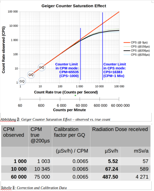
152219 bytes
I think a correction is NOT warranted, because even at CPM=10000 your error is only 3%, while the statistical variation (stdDev) is 1%. And how many people will ever read CPM=10000 from their instrument?
Note that there are 3 lines drawn for dead times of 150, 200, and 250 µs. Around 200µs is what I have seen with the M4011 tube in GQ counter 300E+ using an oscilloscope. Going 50µs up or down is quite a big range, but the impact is minor in the counting range considered here; not worth to take into account.
The famous "3 calibration points" implemented in these GQ counters might have once been intended for the use in such a correction. However, as you can see as the encircled GQs on the lower left portion of the graph show where these points are; they are way too low to be of any relevance.
Typo Error: the 5.52 µSv/h must read 6.52. The 57 mSv/a is correct. |
|
|