| Author |
 Topic Topic  |
|
|
Gelu

Romania
18 Posts |
 Posted - 08/31/2019 : 23:26:33 Posted - 08/31/2019 : 23:26:33


|
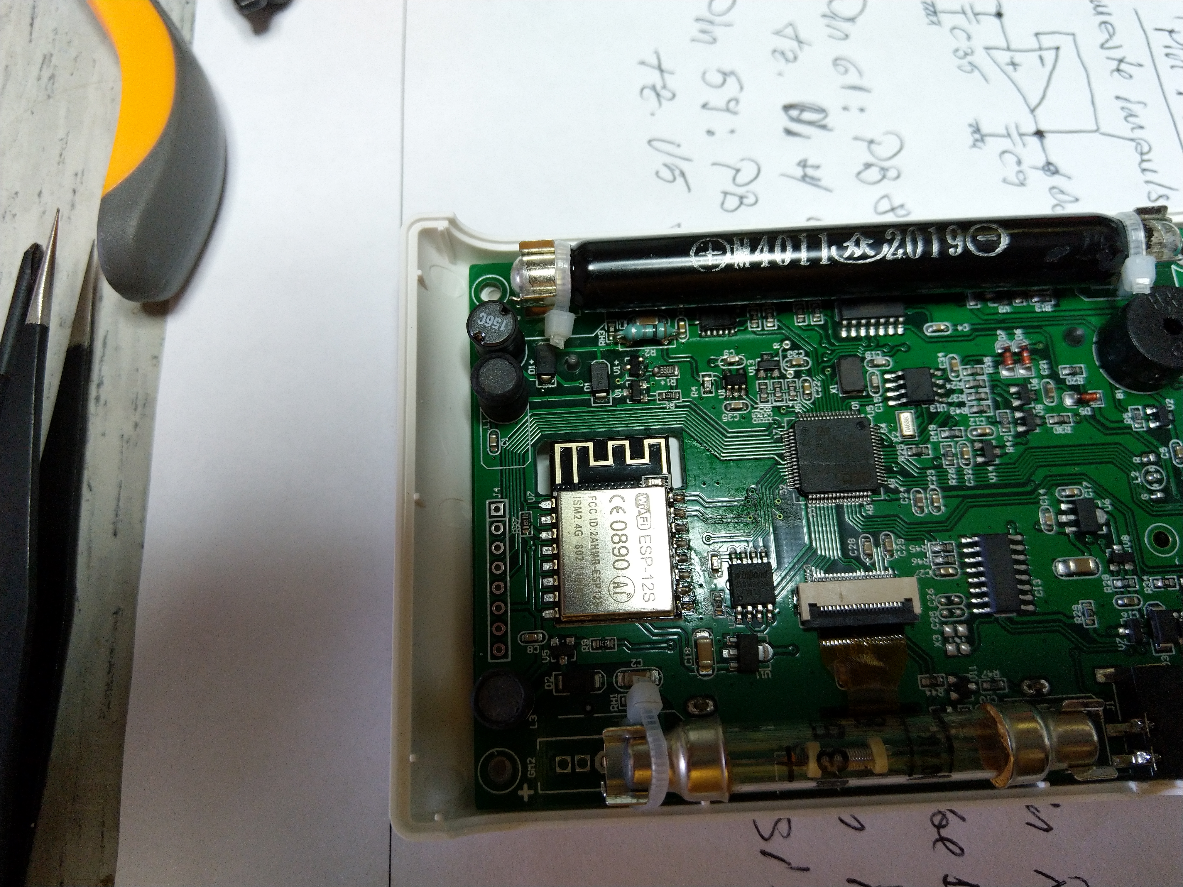
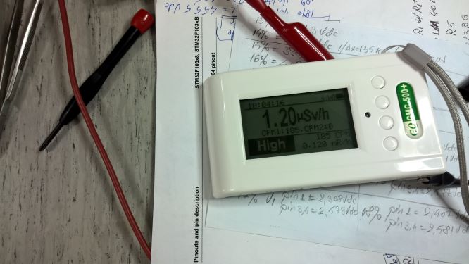
Hi, recently I bought a GQ GMC-500+ on Amazon Germany, and I am very pleased with this device. In the meantime, I got my inspiration from this forum, and I just finished your first DIY, it works great. By the kindness of the support team, we have completed the second of the DIY. I just got the firmware update, Re 2.12. I thought it was ok, but I've seen it here on the forum that someone else had posted the same type of device, with the firmware update, Re-2.13, in which the control voltage of the tube by showing the value in volts on the display. I've asked for the firmware update, Re-2.13, I get it, but it didn't change anything to me, it looks the same to the voltage in percent. I think I'm doing something wrong with the DIY or on the PCB. I have a request if you can help me out with some expert advice. I attach a few pictures of the device. Thank you very much.
Image Insert:
6569135 bytes
Image Insert:
5564645 bytes
|
Edited by - Gelu on 09/04/2019 10:33:14
|
|
| Reply #1
EmfDev

2143 Posts |
Posted - 09/03/2019 : 09:24:37
|
| Hi Gelu, thanks for posting the DIY. And great job making it work! |
 |
|
| Reply #2
Stargazer 40

USA
382 Posts |
Posted - 09/03/2019 : 16:45:47
|
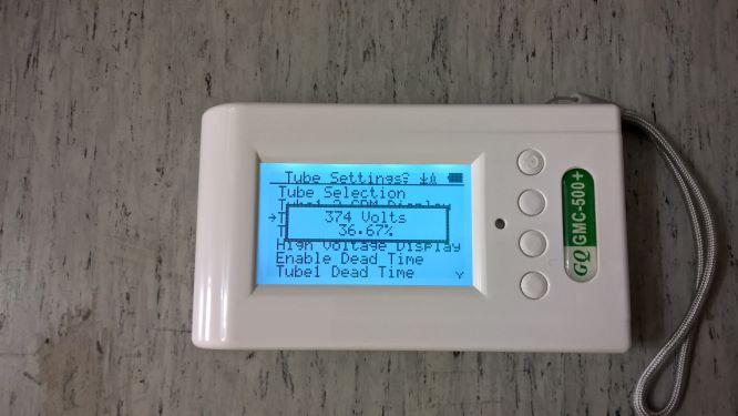
| You need to go to the Init Setup, Tube Settings, High Voltage Display. Then Enabled. |
Stargazer 40 |
|
|
| Reply #3
Gelu
Romania
18 Posts |
Posted - 09/03/2019 : 22:18:46
|
quote:
Originally posted by EmfDev
Hi Gelu, thanks for posting the DIY. And great job making it work!
Hi EmfDev, you're welcome. The first DIY is working perfectly, what's the second DIY, I don't work yet. I'm still not clear if I missed something. Add a couple of pictures with measurements taken on Pin 4 Of U1. Maybe you can help me to fix the problem. Thank you very much.
Image Insert:
41596 bytes
Image Insert:
36193 bytes |
Edited by - Gelu on 09/04/2019 10:49:00 |
|
|
| Reply #4
Gelu
Romania
18 Posts |
Posted - 09/03/2019 : 22:37:55
|
quote:
Originally posted by Stargazer 40
You need to go to the Init Setup, Tube Settings, High Voltage Display. Then Enabled.
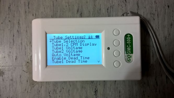
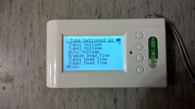
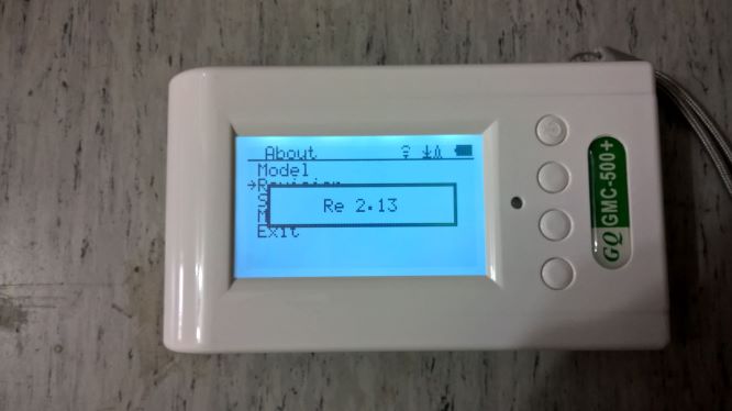
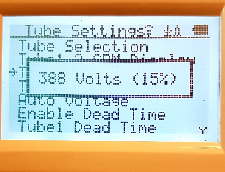
Hi Stargazer 40, thank you very much for the guide, but I think I like the version of my device is the problem. I haven't found all of the High Voltage Display. I'm posting below a few pictures of the device and the version of the software. thank you very much again, I really appreciate it.
Image Insert:
35271 bytes
Image Insert:
32497 bytes
Image Insert:
26331 bytes |
|
|
| Reply #5
Stargazer 40
USA
382 Posts |
Posted - 09/03/2019 : 23:38:11
|
| Agreed, please contact support. I am running a test version of 2.17 Not sure what GQ is using for the distribution version for this feature. |
Stargazer 40 |
|
|
| Reply #6
Gelu
Romania
18 Posts |
Posted - 09/04/2019 : 08:22:58
|
quote:
Originally posted by Stargazer 40
Agreed, please contact support. I am running a test version of 2.17 Not sure what GQ is using for the distribution version for this feature.
Hi Stargazer 40, Thank you, I appreciate it. Of course, I'm going to contact support again. I'm waiting for a response from the EmfDev. Thank you. |
|
|
| Reply #7
EmfDev
2143 Posts |
Posted - 09/04/2019 : 09:37:42
|
| Gelu, does the tube voltage 1 still show percent without voltage? Can you please re-upload the images in #3 reply for some reason they're not showing. |
|
|
| Reply #8
Gelu
Romania
18 Posts |
Posted - 09/04/2019 : 10:25:13
|
quote:
Originally posted by EmfDev
Gelu, does the tube voltage 1 still show percent without voltage? Can you please re-upload the images in #3 reply for some reason they're not showing.
Hi EfmDev, unfortunately, the versions of the software, Re 2.12, respectively, in Re, 2.13, on which I have received from support, it didn't solve the problem. It does not exist in the menu, the function of the High Voltage Display. Re-uploaded the images and some other pictures. Thank you very much. I really appreciate it.
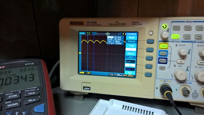
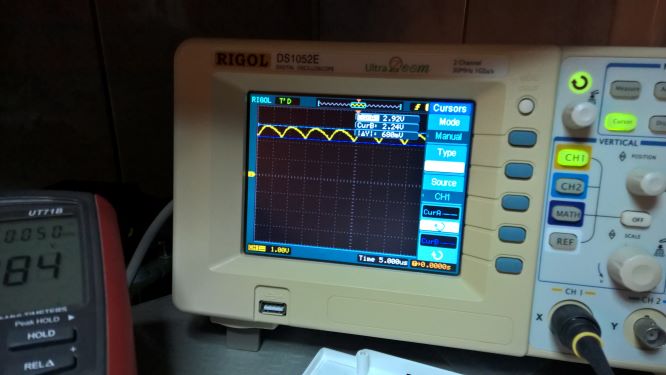
I notice that the photos don't load, I don't know what it is. In the second picture, I measured it with the oscilloscope, the shape of the signal on Pin 4 Of U1, to the CPU
I've done it, I'm very sorry for the inconvenience. I was wrong about the resizing, I'm sorry.
Image Insert:
26853 bytes
Image Insert:
35271 bytes
Image Insert:
32497 bytes
Image Insert:
26331 bytes
Image Insert:
41596 bytes
Image Insert:
36193 bytes |
Edited by - Gelu on 09/04/2019 10:46:42 |
|
|
| Reply #9
EmfDev
2143 Posts |
Posted - 09/04/2019 : 11:01:21
|
| We're still waiting for our engineer to analyze your DIY. And to make sure the resistor is compatible with the HV calculation in the software. |
|
|
| Reply #10
Gelu
Romania
18 Posts |
Posted - 09/04/2019 : 11:14:55
|
quote:
Originally posted by EmfDev
We're still waiting for our engineer to analyze your DIY. And to make sure the resistor is compatible with the HV calculation in the software.
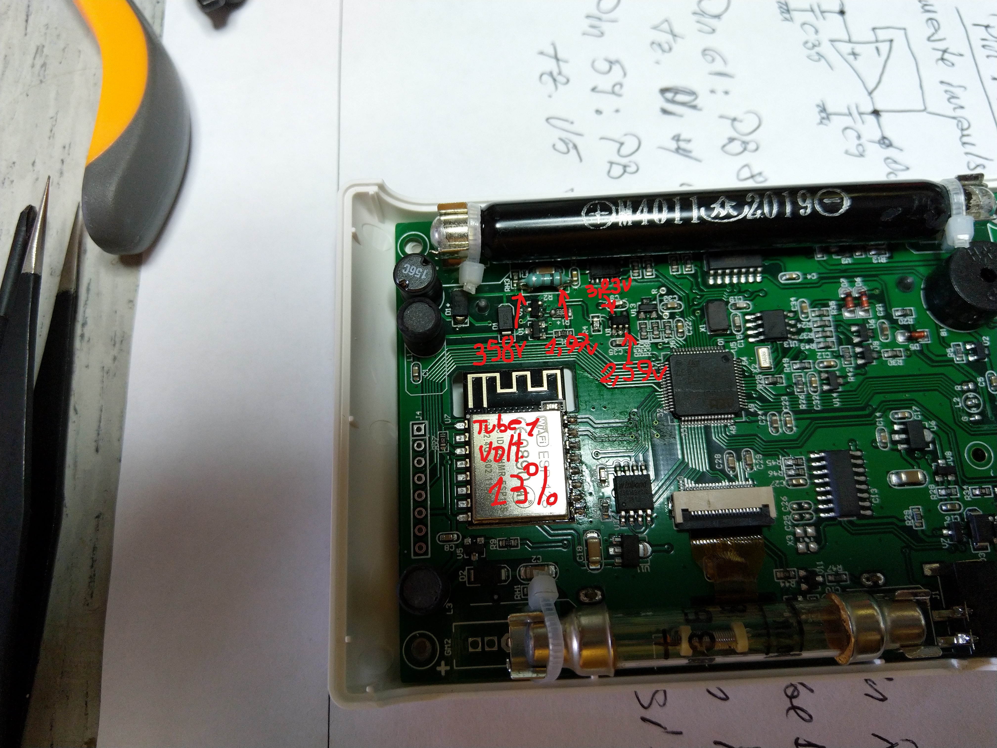
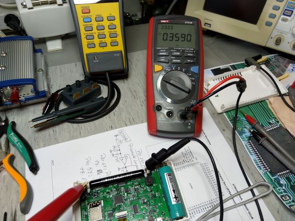
Hi EmfDev, thank you very much for your help. The resistor has a value of 1GOhm. If you go back to my first post, and you're looking at the second picture, you'll notice that I've written down the values, in volts, as measured with a DMM with a 10MOhm impendanta of the input. The value of the High Voltage 358 is a high-voltage, I measured it with the probe of a High Voltage, with the ratio of 1/1000. I'm posting a picture of what I have written above. Thank you very much for your understanding.
P.S.The scope of the DMM is set to the manual is 2 volts.
And one more detail, the value of the volt after resistor of 1GOhm, as measured by the probe, a high voltage is 0.0036 volts. If you might be missing the resistor R4 of 10MOhm on the PCB, the value in volts as measured with a DMM it would be a 3,59 volt. I think the hardware is ok, and I hope to be like that. Thank you.
Image Insert:
64015 bytes |
Edited by - Gelu on 09/04/2019 13:14:54 |
|
|
| Reply #11
EmfDev
2143 Posts |
Posted - 09/04/2019 : 12:29:20
|
I see, was that initially what the support suggested for the DIY?
Hopefully by tomorrow or next day we'll make your unit work. |
|
|
| Reply #12
Gelu
Romania
18 Posts |
Posted - 09/04/2019 : 12:52:36
|
quote:
Originally posted by EmfDev
I see, was that initially what the support suggested for the DIY?
Hopefully by tomorrow or next day we'll make your unit work.
Hi EmfDev, and I hope that the support engineers, in the following analysis, with which I post, to make that version of the software, so that I can read, a High Voltage Display Tube 1. I'd like to think of it as a version of the software to the current Re 2.13 can make control of the High Voltage on the Tube 1 . Now, in the wake investigation that I've done, I can't be sure that it is up and running. I look forward to the resolution of the problem. Thank you very much for your help, I appreciate it. |
Edited by - Gelu on 09/04/2019 12:55:44 |
|
|
| Reply #13
Gelu
Romania
18 Posts |
Posted - 09/05/2019 : 00:25:02
|
quote:
Originally posted by Gelu
quote:
Originally posted by EmfDev
I see, was that initially what the support suggested for the DIY?
Hopefully by tomorrow or next day we'll make your unit work.
Hi EmfDev, and I hope that the support engineers, in the following analysis, with which I post, to make that version of the software, so that I can read, a High Voltage Display Tube 1. I'd like to think of it as a version of the software to the current Re 2.13 can make control of the High Voltage on the Tube 1 . Now, in the wake investigation that I've done, I can't be sure that it is up and running. I look forward to the resolution of the problem. Thank you very much for your help, I appreciate it.
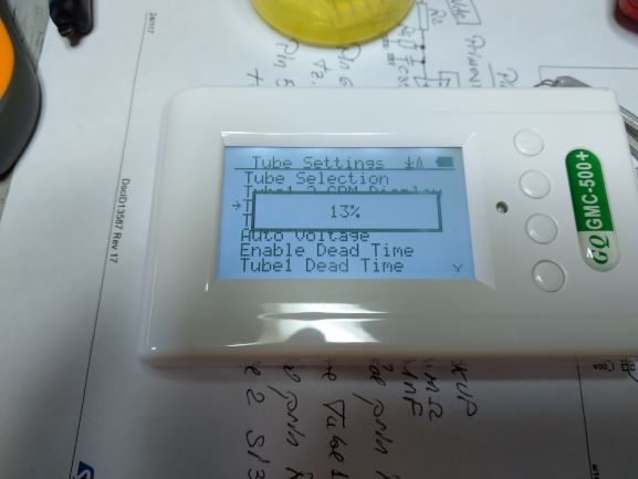
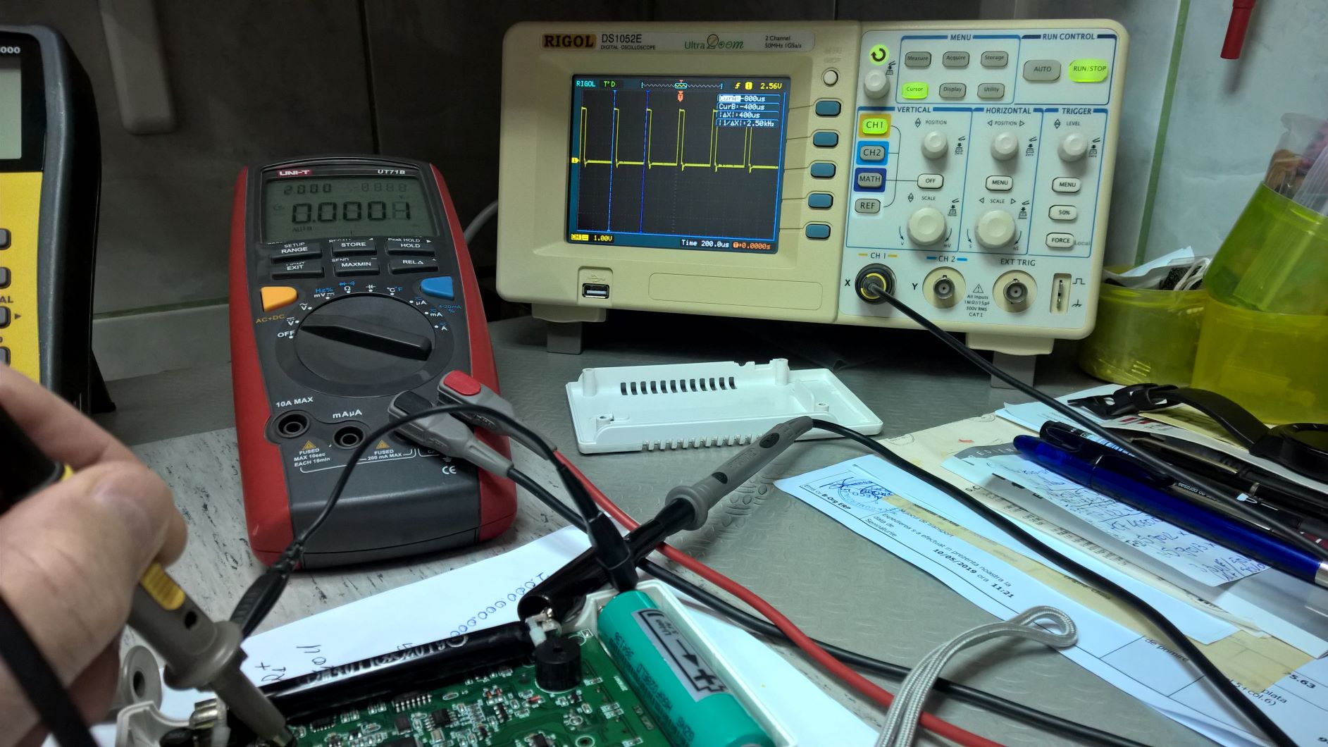
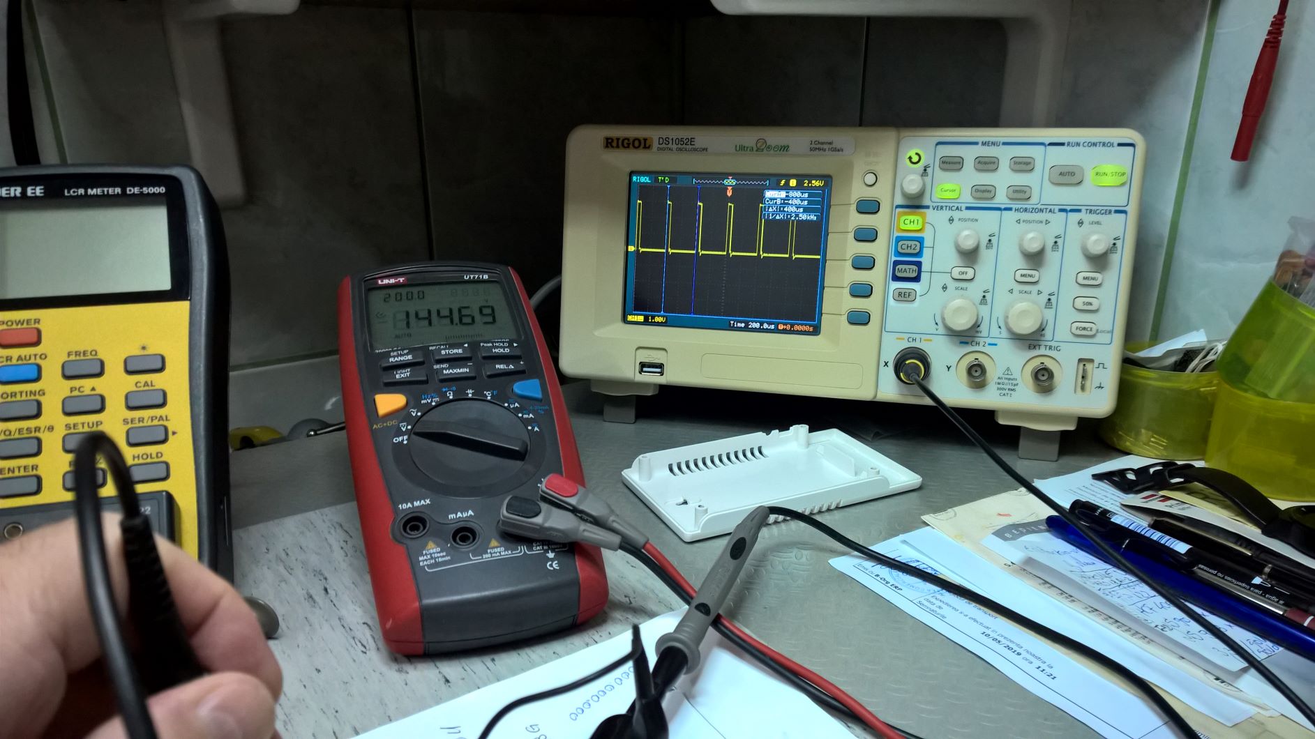
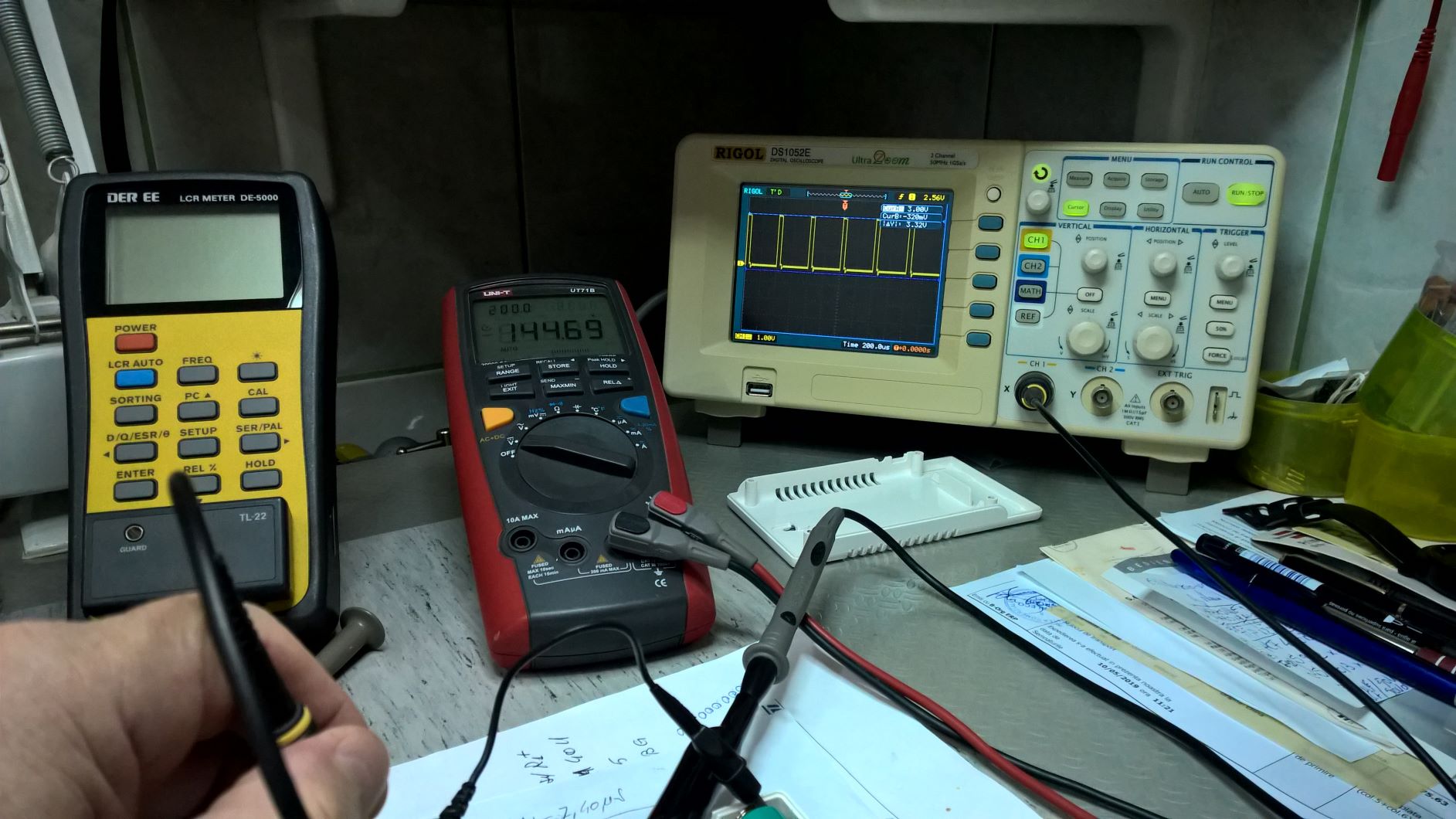
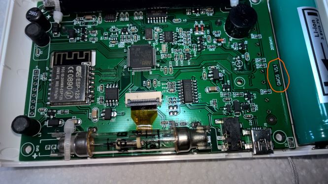
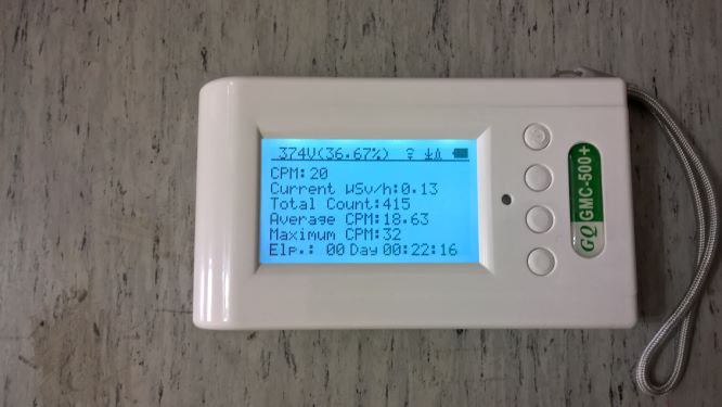
Hi, I'll be back with our next analysis which I have made to Control the High Voltage (DIY), on the Tube 1 M4011. What do I need to take Control of the High Voltage? The CPU analyzes the value of the High Voltage with the help of. Pin 14(PA0-WKUP). If the Tube M4011, asking for an increase in consumption, the value of the High Voltage tends to decrease, then the CPU takes the decision to increase the number of pulses in the base of the transistor U1 through Pin61 (PB8 I/O). We have simulated the collapse of a High-Voltage by measuring it with a DMM at the end of the Tube1. I haven't seen any reaction on the part of the CPU. I think that the CPU doesn't know how to respond if you do not have a built-in program, or if the wiring (DIY), it's not working. I'm posting below the photos of this test. Thank you.
P. S. the Setting of the Voltage Tube1 is at 13% (359 volts to be measured with the probe of a High Voltage.)
Image Insert:
272288 bytes
Image Insert:
243199 bytes
Image Insert:
247980 bytes
Image Insert:
41476 bytes |
|
|
| Reply #14
EmfDev
2143 Posts |
Posted - 09/05/2019 : 09:27:51
|
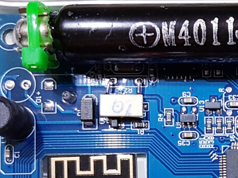
Hi Gelu, I've speaked to our engineer now and said that the circuit should work as it is.
Make sure that these 2 pins are connected together. From the 2.59V and 3rd pin from the left of the processor.
Image Insert:

313557 bytes |
Edited by - EmfDev on 09/05/2019 09:28:46 |
|
|
| Reply #15
Gelu
Romania
18 Posts |
Posted - 09/05/2019 : 10:35:35
|
quote:
Originally posted by EmfDev
Hi Gelu, I've speaked to our engineer now and said that the circuit should work as it is.
Make sure that these 2 pins are connected together. From the 2.59V and 3rd pin from the left of the processor.
Image Insert:
313557 bytes
Hi EmfDev, thank you very much for the suggestion, but I checked it out a long time ago, if there was a connection and that connection is. On the PCB U1 (Pin3,4) is connected to the CPU (Pin14-PA0 WKUP). I'm just curious if you looked at my post from before. There I have drawn two conclusions can be made: 1. the either the CPU does not have the appropriate program for the Control of High-Voltage and High-Voltage Displays. 2. or the circuit of the DIY's I've done , it has a problem. This device has been built with the DIY, that is a project for the future, and it's probably the version of the software is different. The CPU doesn't know what to do with the information received from U1 (Pin3,4), and I think that's the problem. Thank you very much for your understanding. I appreciate it very much |
|
|
| Reply #16
Stargazer 40
USA
382 Posts |
Posted - 09/06/2019 : 14:22:39
|
| Do you have a 5.2 PCB? Shown on the right hand side of the board above. That and the presence of the 1GOhm resistor preclude your first conclusion above. @EmfDev - Did 2.13 upport the voltage readout on text? |
Stargazer 40 |
|
|
| Reply #17
Gelu
Romania
18 Posts |
Posted - 09/07/2019 : 00:09:05
|
quote:
Originally posted by Stargazer 40
Do you have a 5.2 PCB? Shown on the right hand side of the board above. That and the presence of the 1GOhm resistor preclude your first conclusion above. @EmfDev - Did 2.13 upport the voltage readout on text?
Hi Stargazer 40, I have the ver. 5.1 PCB, I'm going to post a picture of the PCB before making the DIY. I just want to let you know that I solved the problem with the help of EmfDev, and the support team. I'm going to post pictures of you with this problem. Thank you very much. I really appreciate it. Thank you
Image Insert:
69175 bytes
Image Insert:
35576 bytes
Image Insert:
33462 bytes |
|
|
| Reply #18
Geo-Johnny
Austria
161 Posts |
Posted - 09/07/2019 : 06:32:31
|
The firmware updates for the GQ devices are already very special and individually tailored. I also have the PCB 5.1 with revision 2.13 on my GMC500+, but I do not have the voltage and percent display on the text screen in the top line. In the setting menu for counter tube 1, I have the volt indicator. STRANGE
 |
Geiger Counters: GMC320+V5 & GMC500+
Geiger Tubes: M4011; SI-3BG; SBT-9; LND712; SBM-20 |
|
|
| Reply #19
Gelu
Romania
18 Posts |
Posted - 09/07/2019 : 22:24:21
|
quote:
Originally posted by Geo-Johnny
The firmware updates for the GQ devices are already very special and individually tailored. I also have the PCB 5.1 with revision 2.13 on my GMC500+, but I do not have the voltage and percent display on the text screen in the top line. In the setting menu for counter tube 1, I have the volt indicator. STRANGE
Hi Geo-Johnny, I'm sorry for the inconvenience, but if you look at the history of the topic, you'll see that I've accomplished one of the two DIY's, but the one with the divider of the High Voltage did not work. I was inspired by the topic of your Ver. 2.13, and I've asked the support team to make it to this update thinking that the problem of non-functionality is here. But it wasn't, it was a matter of some complexity, and with the help of his EmfDev, and the team's support, on this occasion, I wish to thank them one more time, we managed to solve the problem, and I got it with an update of the experimental and that of the Rev. 2.17. Thank you, I appreciate it. |
|
|
| Reply #20
Geo-Johnny
Austria
161 Posts |
Posted - 09/08/2019 : 01:21:45
|
| Thanks Gelu, now everything is much more understandable. I will also try to get a new firmware upate. Sometimes I'm in contact with EmfDev. |
Geiger Counters: GMC320+V5 & GMC500+
Geiger Tubes: M4011; SI-3BG; SBT-9; LND712; SBM-20 |
|
|
| Reply #21
Stargazer 40
USA
382 Posts |
Posted - 09/09/2019 : 08:20:58
|
@Gelu - The DYI you performed was to add the inductor, diode and transistor to the 5.1 board to power up the second leg of the tube 1 power supply? Are you saying that didn't work? Did you get parts from GQ?
@Geo-Johnny - So when you press Tube 1 Voltage you get both the voltage and the percentage shown. You don't have a menu item that says High Voltage Displayed on Text Display. You do need a later version of the firmware I think. |
Stargazer 40 |
|
|
| Reply #22
Gelu
Romania
18 Posts |
Posted - 09/09/2019 : 10:42:08
|
quote:
Originally posted by Stargazer 40
@Gelu - The DYI you performed was to add the inductor, diode and transistor to the 5.1 board to power up the second leg of the tube 1 power supply? Are you saying that didn't work? Did you get parts from GQ?
@Geo-Johnny - So when you press Tube 1 Voltage you get both the voltage and the percentage shown. You don't have a menu item that says High Voltage Displayed on Text Display. You do need a later version of the firmware I think.
Hi Stargazer 40, yes, you are right, that was the first DIY that I've done it and it has worked very well in the first moment. DIY the second, was with the divider for the High Voltage,ability to display the High Voltage. It had problem and I asked for the help of EmfDev and support. Both of the Diy, I bought the parts, not from GQ. Thank you.
|
Edited by - Gelu on 09/09/2019 11:01:08 |
|
|
| Reply #23
Geo-Johnny
Austria
161 Posts |
Posted - 09/09/2019 : 13:00:37
|
quote:
Originally posted by Stargazer 40
@Geo-Johnny - So when you press Tube 1 Voltage you get both the voltage and the percentage shown. You don't have a menu item that says High Voltage Displayed on Text Display. You do need a later version of the firmware I think.
Yes, I think that I need a newer firmware. I have already written the support in this regard today and wait for an answer.
It is also a problem with the big time difference. When I go to sleep, the support is awake.
On my GMC500+, the inductance and the diode are missing in the upper left corner. Hopefully, the high-voltage display on the text screen will still work.
If I need the missing components, would the values be interesting?
 |
Geiger Counters: GMC320+V5 & GMC500+
Geiger Tubes: M4011; SI-3BG; SBT-9; LND712; SBM-20 |
Edited by - Geo-Johnny on 09/09/2019 13:03:54 |
|
|
| Reply #24
Geo-Johnny
Austria
161 Posts |
Posted - 09/10/2019 : 11:34:34
|
I have got the update Re 2.18 for the GMC500+ from the support and now the volts and percent display on the text screen is working - perfect. Photos from the screen and external voltage measurements for comparison will come soon. |
Geiger Counters: GMC320+V5 & GMC500+
Geiger Tubes: M4011; SI-3BG; SBT-9; LND712; SBM-20 |
|
|
| Reply #25
EmfDev
2143 Posts |
Posted - 09/10/2019 : 13:18:47
|
| Just a note 2.18 is basically same as 2.17 but with different HV calibration for older resistors. |
|
|
| Reply #26
Stargazer 40
USA
382 Posts |
Posted - 09/10/2019 : 17:32:09
|
| Just to comment on the missing inductor, diode and transistor. Does not affect the HV readout at all. It is to add another leg to power supply so that more current is available to the tube. With the additional leg of the power supply enabled there will be faster recovery of any voltage drop due to high CPM with Auto Voltage Adjustment Enabled. |
Stargazer 40 |
|
|
| Reply #27
Geo-Johnny
Austria
161 Posts |
Posted - 09/10/2019 : 22:30:31
|
quote:
Originally posted by Stargazer 40
Just to comment on the missing inductor, diode and transistor. Does not affect the HV readout at all. It is to add another leg to power supply so that more current is available to the tube. With the additional leg of the power supply enabled there will be faster recovery of any voltage drop due to high CPM with Auto Voltage Adjustment Enabled.
Thanks for the information, it seems logical. Do you have dates and values of these additional components, so that I can retrofit DIY perfect? For me it is not a problem, I have the necessary equipment. |
Geiger Counters: GMC320+V5 & GMC500+
Geiger Tubes: M4011; SI-3BG; SBT-9; LND712; SBM-20 |
Edited by - Geo-Johnny on 09/10/2019 22:31:13 |
|
|
| Reply #28
Stargazer 40
USA
382 Posts |
Posted - 09/11/2019 : 04:25:27
|
| @Geo-Johnny - You would have to contact support at GQ about the parts. |
Stargazer 40 |
|
|
| Reply #29
Geo-Johnny
Austria
161 Posts |
Posted - 09/15/2019 : 11:13:22
|
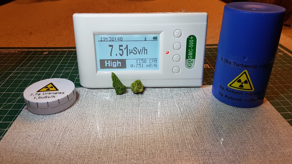
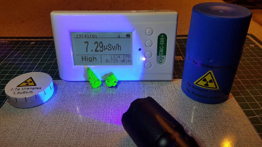
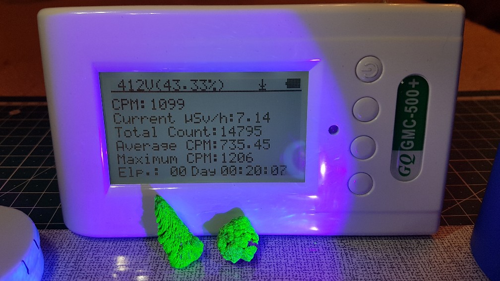
So voil�, here is my GMC500+ with the voltage indicator in the first line of the text screen. In the foreground 2x Autunite pieces and left and right my protective container.
Normal Light
With UV Light
First Line with voltage indicator
 |
Geiger Counters: GMC320+V5 & GMC500+
Geiger Tubes: M4011; SI-3BG; SBT-9; LND712; SBM-20 |
Edited by - Geo-Johnny on 09/15/2019 11:14:16 |
|
|
| |
Topic |
|