| Author |
 Topic Topic  |
|
|
ullix

Germany
1107 Posts |
 Posted - 12/31/2022 : 02:10:52 Posted - 12/31/2022 : 02:10:52


|
With the new firmware, particular in the 600 counter, more settings are being used in the configuration memory, and locations appear to have shifted.
@EmfDev: could you provide an update to the configuration memory?
The last update I have seen was given by ZLM some 4 years ago:
http://www.gqelectronicsllc.com/forum/topic.asp?TOPIC_ID=4948
|
|
| Reply #1
ihab17
Italy
212 Posts |
Posted - 12/31/2022 : 09:47:39
|
In particular the GMC 600+?
Happy new year to all of you |
 |
|
| Reply #2
EmfDev

2143 Posts |
Posted - 01/03/2023 : 12:48:50
|
PowerOnOff, //to check if the power is turned on/off intended
AlarmOnOff, //1
SpeakerOnOff,
IdleDisplayMode,
BackLightTimeoutSeconds,
IdleTitleDisplayMode,
AlarmCPMValueHiByte, //6
AlarmCPMValueLoByte,
CalibrationCPMHiByte_0,
CalibrationCPMLoByte_0,
CalibrationuSvUcByte3_0,
CalibrationuSvUcByte2_0, //11
CalibrationuSvUcByte1_0,
CalibrationuSvUcByte0_0,
CalibrationCPMHiByte_1,
CalibrationCPMLoByte_1, //15
CalibrationuSvUcByte3_1,
CalibrationuSvUcByte2_1,
CalibrationuSvUcByte1_1,
CalibrationuSvUcByte0_1,
CalibrationCPMHiByte_2, //20
CalibrationCPMLoByte_2,
CalibrationuSvUcByte3_2,
CalibrationuSvUcByte2_2,
CalibrationuSvUcByte1_2,
CalibrationuSvUcByte0_2, //25
IdleTextState,
AlarmValueuSvByte3,
AlarmValueuSvByte2,
AlarmValueuSvByte1,
AlarmValueuSvByte0, //30
AlarmType,
SaveDataType,
SwivelDisplay,
ZoomByte3,
ZoomByte2, //35
ZoomByte1,
ZoomByte0,
SPI_DataSaveAddress2,
SPI_DataSaveAddress1,
SPI_DataSaveAddress0, //40
SPI_DataReadAddress2,
SPI_DataReadAddress1,
SPI_DataReadAddress0,
nPowerSavingMode,
nSensitivityMode, //45
nCOUNTER_DELAY_HiByte,
nCOUNTER_DELAY_LoByte,
nDisplayContrast,
MAX_CPM_HIBYTE,
MAX_CPM_LOBYTE, //50
nSensitivityAutoModeThreshold,
nLargeFontMode,
nLCDBackLightLevel,
nReverseDisplayMode,
nMotionDetect, //55
bBatteryType,
nBaudRate,
nCPMSpeakerOnOffCalib,
nGraphicDrawingMode,
nLEDOnOff, //60
nHCPMCAL,
nSaveThresholdValueuSv_m_nCPM_HIBYTE,
nSaveThresholdValueuSv_m_nCPM_LOBYTE,
nSaveThresholdMode,
nSaveThresholdValue3, //65
nSaveThresholdValue2,
nSaveThresholdValue1,
nSaveThresholdValue0,

SSID_0,
//...
SSID_63 = SSID_0 + 63, //68 + 31
Password_0, //100
//...
Password_63 = Password_0 + 63, //100 + 31

Website_0, //132
//....
Website_31 = Website_0 + 31, //132 + 31
URL_0, //163
//....
URL_31 = URL_0 + 31, //163 + 31
UserID_0, //195
//...........
UserID_31 = UserID_0 + 31, //195+31
CounterID_0, //227
//....
CounterID_31 = CounterID_0 + 31, //227 + 31
Period, //259
WIFIONOFF, //260
TEXT_STATUS_MODE,
FAST_ESTIMATE_TIME,
THIRD_PARTY_OUTPUT, //for sending 0xFF per count via serial. This data format used on NETC.com software
HIGH_VOLTAGE_LEVEL_TUBE1, // for adjusting tube 1 voltage
HIGH_VOLTAGE_LEVEL_TUBE2, // for adjusting tube2 voltage
CPM_TUBE_MODE,
CPM_TUBE_DISPLAY,
VOLTAGE_DISPLAY,
DEADTIME_ENABLE,
DEADTIME_TUBE1_HIBYTE,
DEADTIME_TUBE1_LOWBYTE,
DEADTIME_TUBE2_HIBYTE,
DEADTIME_TUBE2_LOWBYTE,
MEDIUMTHRESHOLD_HB,
MEDIUMTHRESHOLD_LB,
HIGHTHRESHOLD_HB,
HIGHTHRESHOLD_LB,
SpeakerVolume,
HV_READING,
TARGET_HV_MSB,
TARGET_HV_LSB,
HV_CALIB,
SS1_0,
SS1_5 = SS1_0 + 5,
SS2_0,
SS2_5 = SS2_0 + 5,
SS3_0,
SS3_5 = SS3_0 + 5,
SS4_0,
SS4_5 = SS4_0 + 5,
ACCURACY_DISPLAY,
DOSE_ALARM_0,
DOSE_ALARM_1,
DOSE_ALARM_2,
DOSE_ALARM_3,
LANGUAGE, |
|
|
| Reply #3
EmfDev
2143 Posts |
Posted - 01/03/2023 : 12:49:41
|
They share with GMC-500/+.
@ihab Thank you!.
HAPPY NEW YEAR TO ALL! |
|
|
| Reply #4
ullix
Germany
1107 Posts |
Posted - 01/04/2023 : 02:36:38
|
@EmfDev: Thank you for the list. However, looking through it, I see a inconsistencies, within the list and to existing counters.
For which firmware version is this valid? And is this supposed to be valid for GMC-500 and GMC-600 counters? But it is not!
Everything before SSID looks ok, but then:
nSaveThresholdValue3, //65
nSaveThresholdValue2,
nSaveThresholdValue1,
nSaveThresholdValue0,
SSID_0,
//...
SSID_63 = SSID_0 + 63, //68 + 31
SSID_0 begins at line 69, and not at 68 as the last line in this segment suggests. And SSID space is 64 bytes wide on fw2.24, and not 31. (which, by the way, is wasting 32 bytes, as IEEE specs sets the width at a max of 32!).
Password_0, //100
//...
Password_63 = Password_0 + 63, //100 + 31
Website_0, //132
Then Password does not start at 100, but at 101. And only on some old firmware, because in fw 2.24 it starts at 133 and is not 32 but 64 bytes wide.
This is what GeigerLog provides, and this is correct:
The configuration as ASCII (0xFF as 'F', other non-ASCII characters as '.'):
  0:0x000   .......d.d    ?&ffu0CC..    ..@.33.?..    ........FF    FFFF...x.F
 50:0x032   F<..F.....    ...d.?....    ..........    ..........    ..........
100:0x064   ..........    ..........    ..........    ...www.gmc    map.com...
150:0x096   ..........    .....log2.    asp.......    ..........    ..........
200:0x0C8   ..........    ..........    ..........    ..........    ..........
250:0x0FA   ..........    ..........    ..FFFFFFFF    FFFFFFFFFF    FFFFFFFFFF
Later on:
Period, //259
WIFIONOFF, //260
TEXT_STATUS_MODE,
FAST_ESTIMATE_TIME,
Period, Wifi are wrong by 2 bytes, Text_status_mode does not exist in old fw, and all are off by some 80 bytes in fw 2.24
Sorry, thanks for the attempt, but this list in not in agreement with any of the fw I have come across!
Is there a way to contact the programmers directly?
|
|
|
| Reply #5
EmfDev
2143 Posts |
Posted - 01/04/2023 : 10:51:33
|
| Hi ullix, this is for 2.41 and above. what you have is maybe lower so yours is still from old config. |
|
|
| Reply #6
ullix
Germany
1107 Posts |
Posted - 01/05/2023 : 04:15:50
|
@EmfDev:
Nope!
Following is a config readout from a most recent GMC600. It has firmware 2.42, so later than 2.41 which you claim is the base for your info.
Compare the positions: XXX... is SSID, YYY... is the Password. Website and url are easily recognizable, and they are NOT where you say they are.
FAST_ESTIMATE_TIME is positioned at 328, far away from your 262! The ASCII value of "<" - also easily visible in the printout at 328 - is 60, i.e. FET is switched off (hopefully).
Detected device  : 'GMC-600+Re 2.42'

2022-12-30 15:41:37.122 DEVEL  : ...269       getGMC_Config: CFG as ASCII:
  0:0x000   ..........    ?....hA ..    ..B....?..    ........FF    FFFF...x.F
 50:0x032   F<..F.....    .....>F.nX    XXXXXXXXXX    ..........    ..........
100:0x064   ..........    ..........    ..........    ...YYYYYYY    YYY.......
150:0x096   ..........    ..........    ..........    ..........    .......www
200:0x0C8   .gmcmap.co    m.........    .........l    og2.asp...    ..........
250:0x0FA   ..........    .03438....    ..........    ..........    ...9550886
300:0x12C   9953......    ..........    ........<.    OK.....P..    .d........
350:0x15E   ...1.....1    ..... ....    ..$..R....    ...).FFFFF    FFFFFFFFFF
400:0x190   FFFFFFFFFF    FFFFFFFFFF    FFFFFFFFFF    FFFFFFFFFF    FFFFFFFFFF
450:0x1C2   FFFFFFFFFF    FFFFFFFFFF    FFFFFFFFFF    FFFFFFFFFF    FFFFFFFFFF
500:0x1F4   FFFFFFFFFF    FF
|
|
|
| Reply #7
EmfDev
2143 Posts |
Posted - 01/06/2023 : 13:22:55
|
| @ullix, the commented numbers are probably wrong and never used. The list I sent is directly copied from an enum typedef from the .h file which starts at 0 and then up to you to count which variables go to where. But the commented numbers are irrelevant of course. Sorry forgot to tell you that. But the sequence should be correct. |
|
|
| Reply #8
ullix
Germany
1107 Posts |
Posted - 01/08/2023 : 01:37:13
|
Sorry, but please explain the magic by which you find out the true positions from the list you gave.
Again, once more, but only two examples:
Your list specifies the Password beginning at 100, though in reality in fw 2.42 it is at 124, a difference of 24
Your list specifies FET at 262, while it really is at 328, a difference of 66.
What is the transformation magic which brings the different numbers in agreement? |
|
|
| Reply #9
EmfDev
2143 Posts |
Posted - 01/09/2023 : 12:15:45
|
The numbers that come after "//" are comments and are not correct and I just forgot to delete them. You are right on your numbering.
The list I pasted are enum variables used as the addresses (I may have edited names a bit) and are used directly when saving data i.e. Save( this "period" value, to this "Period" address). |
|
|
| Reply #10
ullix
Germany
1107 Posts |
Posted - 01/10/2023 : 00:13:23
|
Ok, when I lay it out linearly it begins to make sense; thanks for clarifying.
I now see 7 variables that seem to have to do with the anode voltage(s). Is there an explanation what they do?
HIGH_VOLTAGE_LEVEL_TUBE1, // for adjusting tube 1 voltage
HIGH_VOLTAGE_LEVEL_TUBE2, // for adjusting tube2 voltage
VOLTAGE_DISPLAY,
HV_READING,
TARGET_HV_MSB,
TARGET_HV_LSB,
HV_CALIB,
And then we have the 20 bytes SS1...SS4 which I have not seen before. They seem to be in use, but what for?
|
|
|
| Reply #11
Damien68
France
780 Posts |
Posted - 01/10/2023 : 02:53:09
|
quote:
Originally posted by ullix
TARGET_HV_MSB,
TARGET_HV_LSB,
Is there an active regulation made by the software? |
Mastery is acquired by studying, with it everything becomes simple |
|
|
| Reply #12
EmfDev
2143 Posts |
Posted - 01/11/2023 : 12:12:46
|
[quote][i]Originally posted by ullix[/i]
[br]
HIGH_VOLTAGE_LEVEL_TUBE1, // for adjusting tube 1 voltage
HIGH_VOLTAGE_LEVEL_TUBE2, // for adjusting tube2 voltage
VOLTAGE_DISPLAY,
HV_READING,
TARGET_HV_MSB,
TARGET_HV_LSB,
HV_CALIB,
[/quote]
These are all for the tube 1 and 2 voltages.
[quote]
And then we have the 20 bytes SS1...SS4 which I have not seen before. They seem to be in use, but what for?
[/quote]
For screenshots.
|
|
|
| Reply #13
EmfDev
2143 Posts |
Posted - 01/11/2023 : 12:15:09
|
[quote][i]Originally posted by Damien68[/i]
[br][quote][i]Originally posted by ullix[/i]
TARGET_HV_MSB,
TARGET_HV_LSB,[/quote] Is there an active regulation made by the software?
[/quote]
What do you mean by active regulation? These params are related to automatic voltage adjustment feature. |
|
|
| Reply #14
ullix
Germany
1107 Posts |
Posted - 01/12/2023 : 00:23:25
|
@EmfDev: thanks. But which of these values is used as a readout of the actual value for tube#1, and which for tube#2?
All of these are single-byte values, but to present a voltage of e.g. 400V I'd expect a double byte value?
|
|
|
| Reply #15
EmfDev
2143 Posts |
Posted - 01/12/2023 : 14:48:03
|
| target_hv is the real voltage for the newer versions with hv feedback. older versions does not have this so uses high_voltage_tube_level (from tube voltage %). |
|
|
| Reply #16
ullix
Germany
1107 Posts |
Posted - 01/13/2023 : 02:17:44
|
quote:
target_hv is the real voltage for the newer versions with hv feedback. older versions does not have this so uses high_voltage_tube_level (from tube voltage %).
But this is what the users gets to see on the display of the counter as the anode voltage being effective in this moment?
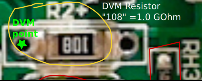
On a 600+ counter I see a 1 GigaOhm resistor. Which finally allows the user to check on the voltage, which is a really nice modification! I assume you have an onboard ADC, and its reading is given as the feedback. So, no voltage regulation in the sense Damien was asking, but the user is the "Control circuit"?
Am I right that measuring at the "DVM point" as star-marked in the picture should give you a reading which multiplied by 100 gives the anode voltage? I don't recognize any capacitors around this resistor, so it should also allow to follow the dynamics with an oscilloscope when a high count rate is measured?
 |
|
|
| Reply #17
EmfDev
2143 Posts |
Posted - 01/13/2023 : 17:28:31
|
1. target_hv is what voltage the counter needs to get to �5V. If the load goes higher the voltage goes lower, so then the device will try to get back to target_hv.
2. there is adc for reading the high voltage. You can check with the current firmware if your device has one by going to Tube Settigns -> Voltage. If it displays the voltage e.g. 401V (35%) then it does have the resistor and supports voltage regulation.
3. According to our expert, it is better to measure the voltage on pin4 of U1. the voltage is usually around 215x less than the real high voltage. example: pin 4 = 0.59 then the high voltage = .59 x 215 = 129V. Pin 4 is on the 2 pin side of U1. Pin 5 (the other pin) is 3V. |
|
|
| Reply #18
ullix
Germany
1107 Posts |
Posted - 01/15/2023 : 00:28:41
|
quote:
1. target_hv is what voltage the counter needs to get to �5V. If the load goes higher the voltage goes lower, so then the device will try to get back to target_hv.
What is "�5V"?
Doesn't this mean that you do have an active regulation of the anode voltage? I think a few posts ago you said the opposite?
quote:
3. According to our expert, it is better to measure the voltage on pin4 of U1. the voltage is usually around 215x less than the real high voltage. example: pin 4 = 0.59 then the high voltage = .59 x 215 = 129V. Pin 4 is on the 2 pin side of U1. Pin 5 (the other pin) is 3V.
Yes, works.
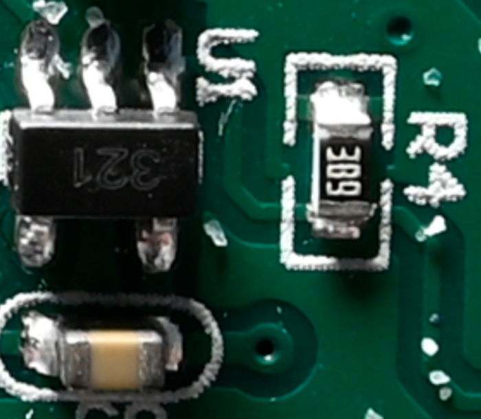
On fiddling with the counter we saw "R4" labelled as "389". That would be 38 GigaOhm. Really? This seems awfully high. Or are we misinterpreting anything, or is that even a defective labeling?
 |
|
|
| Reply #19
ihab17
Italy
212 Posts |
|
| Reply #20
Damien68
France
780 Posts |
Posted - 01/17/2023 : 00:29:25
|
quote:
Originally posted by ihab17
Also according to this https://www.digikey.it/en/resources/conversion-calculators/conversion-calculator-smd-resistor-code it is 38 G Ohm.
I've been tinkering and working in electronics for more than 40 years, but without knowing it, you've given me a beating.
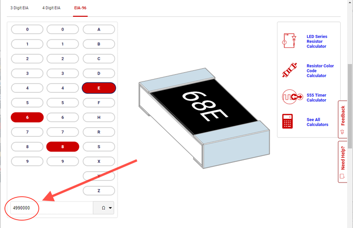
thanks to your link to digikey, if we use the EIA-96 encoding, and if we read the resistance marking from the other direction, that is to say '68E' and not '389' we then obtain according to the encoding EIA-96: 4.99 Mohms. I did not know this standard, I usually use smaller boxes (0402) where there is no marking on them.
which with the 1G resistor gives a division factor of (4.99+1000)/4.99 = 201.4
 |
Mastery is acquired by studying, with it everything becomes simple |
Edited by - Damien68 on 01/17/2023 00:46:05 |
|
|
| |
Topic |
|
|
|