| T O P I C R E V I E W |
| ikerrg |
Posted - 09/04/2018 : 11:00:31
Hello,
I am considering the addition of a hardware switch to my GMC-500+ to easily disconnect the M4011 tube without opening the case. I need a small switch, or even a jumper type, but it has to be accessible from the outside, and look neat (not a tacky addition fixed with insulating tape). I plan to cut a small hole in the case for that purpose.
My question is more related to the insulating requirements. In principle, the switch would be under 400 V when opened, and therefore some good insulation would be required. However, given the very high impedances in series when the switch is open (the HV circuit internal impedance, the tube internal impedance and the anode resistor) I think that any kind of low voltage switch would be adequate. What do you think?
Have you checked the minimum distance between terminals to interrupt the circuit when the tube becomes conductive?
I am considering these items or similar:
https://www.ebay.co.uk/itm/371922813525
https://www.ebay.co.uk/itm/273323806940
https://www.ebay.co.uk/itm/142325630556
https://www.ebay.co.uk/itm/163151474419?var=462315729852
Many thanks.
|
| 14 L A T E S T R E P L I E S (Newest First) |
| EmfDev |
Posted - 09/14/2018 : 15:33:42
Hi ikerrg, I just sent you an email. You might want to check your profile email before you drill a hole. |
| ikerrg |
Posted - 09/14/2018 : 15:13:06
Yes, I plan to drill a hole to have external access to the switch (that is the whole point of the mod). But I do not expect to need to remove the switch. I think that not having a way to disconnect the high sensitivity tube is the biggest flaw in this device with two tubes of such different sensitivities connected in parallel.
Thanks for the idea, the hot glue gun might be better than epoxy glue, as it is not permanent in case of a failure.
|
| EmfDev |
Posted - 09/14/2018 : 14:57:00
Maybe use a hot glue gun to glue switch 2(bigger 1) so you can remove it later when not needed.
Also you can drill a hole outside the case so you can just manually switch it on or off. |
| ikerrg |
Posted - 09/14/2018 : 13:18:13
OK, guys, I need some advice about this. I have a couple of types of switch. One is very small, for PCB mount, and it looks perfect to do a very neat job, with very short wires and distances between components. I can attach it to the PCB using epoxy resin (Araldite type) and I can connect the new 3 MOhm resistor directly to it without additional wires. The hole in the plastic enclosure would need to be on the side, and a small stick would be needed to change the switch position after assembly.
Image Insert:
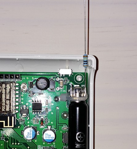
53958 bytes
The other switch is much bigger. Its position in the plastic enclosure could be in the back (close to the hole used to hung the GMC-500+ on a wall), but it would need to be fixed to the same plastic enclosure (the lid), and therefore it would be very difficult to assemble after soldering. So the only possible position would be again on the side, like the other switch, but supported on the plastic enclosure instead of on the PCB. To change the position of this switch one finger would be enough, as it is much bigger and it could protrude to the outside. The problem about this switch is that the contact does not look as good (solid) as with the other switch (which is designed to be a PCB switch, like a mainboard jumper), so my concern is that it might add some noise to the system if the contact is not good enough.
Image Insert:
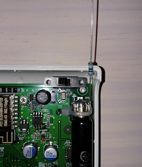
60166 bytes
What are your comments about the possible layouts? I want to be very sure about what I am going to do, because after desoldering the R2 resistor there is no way back! I could never re-solder it again, it is minuscule!
|
| Stargazer 40 |
Posted - 09/07/2018 : 15:01:58
I too from what I've read thought the anode resistor was there to separate the GM tube from stray capacitances that could damage the tube from the PS side of the circuit if not present. |
| ikerrg |
Posted - 09/07/2018 : 09:10:52
I didn't know that the problem was the capacitance of the wire from the anode resistor to the tube. In ZLM's video (reply #79 in http://www.gqelectronicsllc.com/forum/topic.asp?TOPIC_ID=5369), the LND7317 tube is connected by very long wires to the terminals (therefore also to the anode resistor), and it seems to work OK. I also remember that the user the_mike connected an external SBM-20 tube to the SI-3BG terminals with long wires, and the readings were also OK. I understand that the capacitive effect (to ground) would be big if the wire runs close to a grounded surface of the PCB. In fact, I think that a long wire should add inductance in series to the system.
In any case, I need to test the switch just to be sure that the connection is solid and does not introduce any noise due to a bad contact. I plan to test different switch types. And then I have to think how to support the switch to the plastic cover or the PCB. I have some ideas, but I have to be careful not to spoil the neat finish of the GMC-500+.
|
| ullix |
Posted - 09/07/2018 : 08:37:11
quote:
In any case, before unsoldering anything, I will check that the tube works properly in series with the switch, by measuring background and higher radiation for some time with geigerlog as you proposed.
If done as I proposed it is not necessary.
Because, what matters is the capacitance of the lead from the resistor to the tube. Can't get any shorter as in GQ's layout, which is really good in that aspect. But in my proposal the lead from the new R2 resistor to the tube is just as short.
If there is capacitance in the switch and the other wiring, it would be in the order of 100pF in parallel to the C2 cap of 10000pF.
100pF on the wrong side of R2 would be a real issue, but not in this config.
|
| Stargazer 40 |
Posted - 09/06/2018 : 17:47:18
I very much like ullix's approach to this mod. I looked at the space for that larger cap and wondered if it might provide some room to work. ikerrg, if the PCB is the same in both corners (ie., has a number if '+' holes) you could attach the positive side wire/anode res of the switch to the underside of the board instead of the top side under the tube. Make it easier. |
| ikerrg |
Posted - 09/06/2018 : 09:35:05
Thanks ullix. I see your point discarding the tiny resistors, as it is almost impossible to manually solder them. I only plan to add a switch to the M4011 tube (the SI-3BG is so insensitive that it would never reduce the voltage of the HV network), so I suppose that I only need to unsolder R2 and solder the wires to the left hole of the C3 area and somewhere in the + terminal of the M4011 tube (this one does not have through holes close to the + terminal like the SI-3BG tube).
In any case, before unsoldering anything, I will check that the tube works properly in series with the switch, by measuring background and higher radiation for some time with geigerlog as you proposed.
|
| ullix |
Posted - 09/05/2018 : 23:31:06
I refer to my 500+ Review post http://www.gqelectronicsllc.com/forum/topic.asp?TOPIC_ID=5369 and the very first picture as well as to ZLM's reply #26 circuit diagram.
Yes, there is an anode resistor for each tube, called R2 and R4, each one 3M. You see them as the most upper left and lower left items in the pic.
Each tube also has one capacitor immediately below, resp above these Rs, labeled C2S and C3S, in the circuit diagram as C2 @10nF. Thus the two are parallel. They are for smoothing the HV.
These caps are next to an open space labeled C2 and C3, resp, which might have been provisions for using a larger cap in lieu of C2S and C3S. The right side is GND, the left side carries HV. Good thing is they provide through holes.
What I would do to implement your ideas:
1) unsolder R2 and R4 and discard. Verify you have not inadvertently shortcut the two ends with solder!
2) Solder a wire into the left hole of the C2/C3 space.
3) Solder a wire into one of the free holes next to or underneath the plus ends of the tubes.
4) to the end of this wire solder a 3M resistor. Smallest wattage ok.
5) connect the other end of this resistor and the other end of the wires from C2/C3 to your switch(es).
|
| ikerrg |
Posted - 09/05/2018 : 08:33:55
I think I recall that ullix said that there were two anode resistors, one for each tube. Am I right? In fact, I think I can see them in the first post of http://www.gqelectronicsllc.com/forum/topic.asp?TOPIC_ID=5369
Thanks for the tip, ullix. The only problem is that I have to desolder the resistor to put the switch in series, which is not as easy/risk free as just connecting the tube terminal to the switch. Those resistors are tiny, and my desoldering skills are not the best.
I will show pictures and results whenever I find time to do the DIY job. First I need to find the best switch, for which GQ's input would be much appreciated. Any warning or ideas, GQ?
Edit: I've found this kind of switch (DIP) very typical in old PC mainboards. It is very tiny: https://www.ebay.co.uk/itm/263210789529?var=562204844424
|
| Stargazer 40 |
Posted - 09/05/2018 : 06:42:16
quote:
Originally posted by ullix
I do strongly recommend to insert the switch between HV and anode resistor to avoid any new capacitive issues. If you can't, do a long-term measurement after installation and test Poisson to verify that it is still proper Poisson !
Well, if the same anode resistor is used for both tubes, then you want the switch on the tube side. There the tube will be open and not involved. We want to be able to remove the M4011 tube from the circuit. We don't need to remove the SI3BG from the circuit given it's low sensitivity. It will not impact the performance of the M4011. If each tube has it's own anode resistor I think I agree with ullix.
@ZLM - does each tube have it's own anode resistor or do they share R4? |
| Stargazer 40 |
Posted - 09/05/2018 : 04:54:59
Thanks for acting on this. Please show pictures of your entire installation process. Hopefully I can find your chosen switch on US Ebay. |
| ullix |
Posted - 09/05/2018 : 00:52:43
Given that apparently no HV protection of any kind is implemented in the counters, the HV insulation does not seem to be hot issue.
I do strongly recommend to insert the switch between HV and anode resistor to avoid any new capacitive issues. If you can't, do a long-term measurement after installation and test Poisson to verify that it is still proper Poisson ! |
|
|